
Many potential programmers are turned away from G-Codes when they see a typical program. G-Code seems pretty cryptic at first glance, however by learning just a few codes you will be able to read about 90% of a typical program. For instance, by learning the code G01 (Linear cutting move), you would probably be able to figure out that the following code excerpt cuts a square with one corner located at the origin:
…
G01 X0.0 Y0.0 F8.0;
G01 X2.0 Y0.0;
G01 X2.0 Y2.0;
G01 X0.0 Y2.0;
G01 X0.0 Y0.0;
…
Warning! Do not run any code on a real machine until you know exactly how your particular machine will interpret the program.
As the saying goes, a little knowledge is a dangerous thing. It would be very dangerous to run the code excerpt as it is. As you will see, there are many settings that affect how the controller interprets the G-Codes, and these must never be assumed.
Also, this code could be simplified a little further as we will soon see. But the general idea is pretty easy to follow once you know what G01 means. In the following pages, we will look at individual codes like G01 in detail, and see how we can eliminate any assumptions that could result in dangerous or unexpected machine movements.
A code snippet like the one above leaves too much room for doubt as to how the machine will react. For example, do the coordinates represent actual locations, or do they represent a distance to move (absolute or incremental)? Are they in reference to the machine origin or some other coordinate system? How fast should the tool go, and which tool should the machine use? These kinds of questions are cleared up by adding some more detail to the code. The following code is a little more realistic. Don’t worry if you don’t understand much about it at this point, we will go through each part in the following pages.
% N010 (BEGIN HEADER);
N020 (DESCRIPTION: PART NUMBER U23-0020 REV C, MILL TOP SIDE);
N030 (SEE SETUP DESCRIPTION ON PROCESS ROUTING SHEET);
N040;
N050;
N070 G17 G20 G40 (XY PLANE, INCH MODE, CANCEL CUTTER COMP);
N080 G55 G80 G90 G94 (ORIGIN, CANNED CYCLE CANCEL, ABS., FEED PER MIN.);
N090 G43 (TOOL LENGTH COMPENSATION ON);
N100;
N110 (END HEADER);
N120;
N130 T01 H01 (TOOL NO. 1, TOOL OFFSET 1);
N140 M06 (TOOL CHANGE);
N145 M02 (SPINDLE ON);
N150 G00 X-0.5 Y-0.5 (RAPID TO POINT NEAR ORIGIN);
N160 G01 X0.0 Y0.0 F8.0 (POSITION TOOL OVER ORIGIN);
N170 Z0.0 (LOWER TOOL TO Z0.0);
N180;
N190 X2.0 Y0.0 (BEGIN CUTTING RECTANGLE);
N200 Y2.0 ;
N210 X0.0 ;
N220 Y0.0 ;
N230;
N240;
N250;
N260 (BEGIN FOOTER);
N270 G01 Z8.0000 (BE SURE 8.00 IS A SAFE RETRACT);
N280 M30 (PROGRAM STOP AND RESET);
%
The code above commands the tool to follow the path shown here. Notice that it is important to know that your program will not collide with workholding or other machine components. It is the job of the programmer to follow safe practices and eliminate any potentially dangerous assumptions in programming.
G-Code Syntax
Machines to not speak English, Spanish, French, German, or Chinese. The only language a machine knows is one of electricity. The purpose of G Code is to bridge the gap between the ones and zeros the machine understands to something more readable for a human being. While it may seem a little hard to read sometimes, it is much easier to read G Code than a series of binary numbers.
File Format
G Code can be written in any text editor that supports an ASCII text file. An example of this is Microsoft’s Notepad program. Standard word processing software such as Microsoft Word or Open Office Writer can be used to write ASCII text files, but they must be explicitly told to save in that format — standard document formats will not be read by a CNC controller.
Word address format
The basic format of a G Code statement is called word address format. This means each command is made up of “words.” A word is a letter/number combination such as G21. G is the address of the word. It says to the controller, “look at your list of ‘G’ commands, pick command number 21 and get ready to do it.” This particular command (G21) tells the controller to interpret distances as millimeters.
Arguments/Parameters
When the controller sees G21 in a program, there is only one thing it must do: it must interpret distances as millimeters. Some commands require specific motions, distances, rates, or times. These commands take arguments. An argument answers questions raised by issuing a command. For instance the command G01 is a command to move in a straight line to a particular point at a particular rate. When the controller sees G01 it expects to get some information about the destination point and the speed at which to travel. For example, a G01 command would look something like this:
G01 X2.0 Y3.0 Z0.0 F8.0;
The controller now knows to go to the point (2.0, 3.0, 0.0) at a rate of 8.0 inches per minute. (This command could actually be interpreted differently depending on the commands that preceded it. This will be discussed in more detail throughout this chapter.)
Not all arguments are required all the time. For instance, if the programmer did not wish to move the Z axis at all, he or she could omit the argument Z0.0 from the G01 command.
Note:
Be sure to consistently use a decimal point. Most controllers are configured to interpret numbers without a decimal point as being ten thousandths of an inch. To a controller, X3 means X0.0003.
This can make a BIG difference between the expected motion and what actually happens!
Blocks
A block is a group of codes that are executed together. Programs are always broken down into blocks. You may have noticed the “ ; ” at the end of the G01 statement above. This is called the end of block (EOB character). This signals to the controller that it is now time to perform the requested information. Some codes can be grouped together in the same block while others cannot. Some controllers will add EOB characters to a text file automatically.

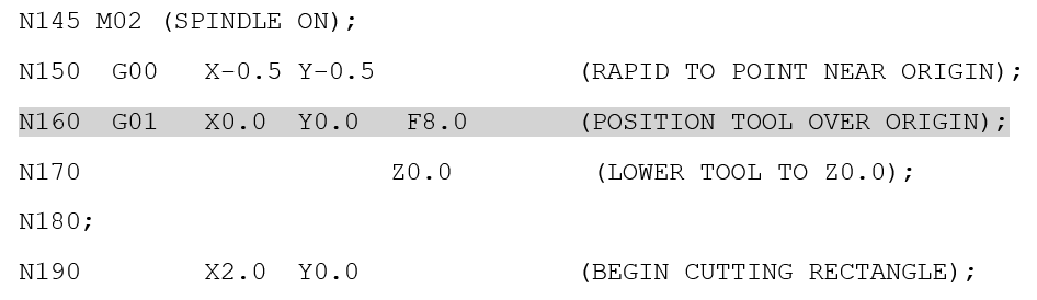
In the code snippet below, line N160 is a block. It will execute before performing the Z move in line N170. This tool will move in the XY plane only while it executes N160. When the tool is in the X0.0 Y0.0 position, it will advance to the next block (line N17) and move straight down. If the Z0.0 text had been placed in line N160 with the XY move, it would have moved diagonally downward.
Understanding the way blocks execute is fundamental to understanding G-code.
Special Characters
In addition to the EOB character that defines the end of a block, there are several other characters that have special meaning to the controller. Among these are the open “ ( “ and close “ ) “ parentheses. Text that falls within these characters is known as a comment. Comments are completely ignored by the controller, even if they contain code that would otherwise be executed. Comments are used to provide important information to setup personnel, operators, and other programmers. Comments may give important information about the setup or machining operations. Most controllers will return an error if the number of opening and closing parentheses does not match.
Comments are also used to make the program more readable to people. It is hard for human beings to look at G Code and immediately understand what the machine will do. Comments can be used to explain unusual or unexpected operation. Comments may also be used to break the code into sections (such as separate header and footer sections).
The percent sign “ % “ is used to tell the controller where the beginning of the program is. It is a good idea not to include any other text before this character as this may cause the controller to return an error. This character also marks where the end of the program is.
There are other special characters such as the slash code “ / “ and pound sign “ # “ , but these are not important to the beginning programmer. These will be covered in later sections.
Whitespace
In general, whitespace (space and tab characters) are ignored by the controller. They may even be stripped out when the program is loaded onto the machine. However, proper use of whitespace can make a program much easier to read, and make it easier to troubleshoot when things do not go as expected. Whitespace can be used to align X , Y, and Z coordinate values. This makes it easy for a person to mentally see how the program will run. Whitespace is especially important in code that is manually maintained (as opposed to code generated from a Computer-Aided Manufacturing (CAM) program).
G Address – Preparatory Functions
The G address codes are what give G code its name. Most of the primary functions of the machine are controlled by codes that start with the letter G (have a G address). The G address codes (or G Codes for short) are called preparatory functions because they initiate processes that must be further interpreted by the machine to do a specific task. G codes often initiate processes that require calculation, such as calculating the points required to generate the path of an arc.
M Address – Miscellaneous Functions
The M address codes are miscellaneous functions. Most of these commands operate physical switches to turn things on or off. For instance, M03 turns the spindle on clockwise and M05 turns it off. The action of an M code occurs only when the controller encounters the EOB or end of block “ ; “ character. To avoid conflicting settings, controllers only allow one M code in each block.
Other Addresses
In addition to the G and M addresses, other letters are used to signify various actions and settings to the controller. The most common are outlined here, the rest will be discussed as they relate to specific commands.
Line Numbers (N)
Line numbers ( N ) are a means of referring to a specific point in the program. They are a sort of “serial number” for each block or line of code. More advanced programming techniques will make use line numbers as a means of pointing the controller to sequences of code. Unless the line numbers are being used in this way, most controllers do not require them, and often they will automatically assign line number if they do not already exist in the code. The format of a line number is N followed by a three or four digit number (N010). Line numbers often increment by values of ten to allow new lines to be entered in between existing blocks of code.
Spindle and Tool Addresses (S, T, H & D)
The letters S, T, H and D are used to set variables related to the spindle and tools. S represents the spindle, and depending on various other settings, can represent the speed of the spindle in revolutions per minute, or the surface speed in a distance per minute. H and D will be covered later in the discussion about tool length and diameter compensation.
The feed rate (the speed at which the tool moves within the workpiece material) in inches per minute of millimeters per minute are specified with an F address.
T is the address for a particular tool number. The T address does not initiate a tool change itself, but relies on an M code (M06) to actually change the tool. The H address is used to keep track of the differences in tool lengths on a milling machine. The T and H addresses are discussed in more detail in Chapters 3 and 4.
Modal or Non-Modal
You may have noticed that there are different kinds of switches that we use every day to turn things on and off. A light switch mounted on the wall is a type of toggle switch. When you turn it on, it stays on until somebody comes along and turns it off. A car horn is a different type of switch. Thankfully a properly functioning horn only makes sound while it is being pressed. This type of switch is known as a momentary contact switch. Similarly, there are two kinds of G-codes that work much the same way. These are known as modal (toggle switch) codes and non-modal (momentary contact) codes. Modal codes stay on until another code turns them off.
It is vital to understand that modal codes stay active even after a program has ended. This is one reason standard headers are so often used in industry. These headers clear out the codes that would be dangerous to the operation of the machine if their setting was not set to a known condition. An example of a modal code is G20. G20 sets the units of the machine to inches (G21 sets to mm). If a programmer wrote a program for a machine that was assumed to be in millimeters, he or she would be in for a very dangerous surprise if the machine interpreted the values as inches. Always be sure to use a header to set explicitly any modal commands that would affect execution of the program.
Non-modal commands, however, are only active during the block in which they exist. An example of a non-modal command is G04 (dwell). G04 is often used to pause a drilling operation at the bottom of a hole for a certain length of time so the bottom of a hole can be made completely smooth. If a G04 is put in one line of code, it only pauses the operation(s) initiated by that block. The following blocks will not be paused unless they include their own G04 command. Most machine tool manufacturers distinguish between modal and non-modal commands in their programming manuals.

Recent Comments