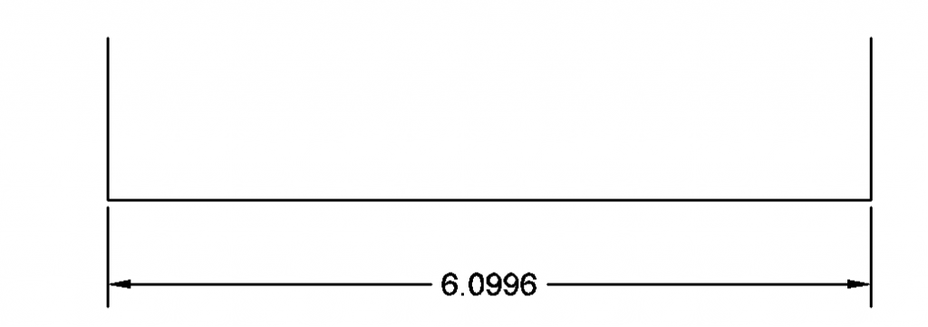
The length of the blank (unbent part) below is somewhere between the length of the interior and the length of the exterior.
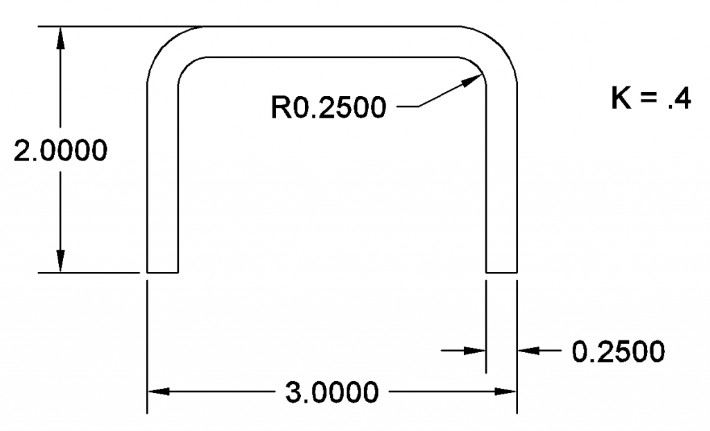
When the part is bent, the outside of the bend is placed in tension and the inside is placed in compression. The boundary between these zones is in neither tension nor compression. It is called the “neutral axis” and its length does not change during bending. The volume of the compressed and pulled material is unchanged, it flows outward (compression zone) and inward (tensions zone) along the bend.
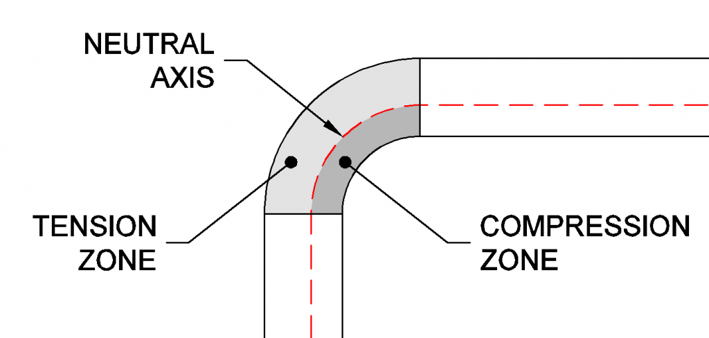
It would be convenient if the neutral axis lay perfectly in the center of the sheet, but this only happens when the bend radius (the internal radius) is more than three times larger than the material thickness. The neutral axis is generally shifted toward the inside of the bend. The neutral axis is located by multiplying a correction factor, the k-factor, by the material thickness. This factor is smaller for tight bends. The neutral factor is a function of the bending die arrangement, the sheet thickness, the bend radius, and the properties of the material itself. K-factors are generally found empirically.
K factors for mild steel air bent in a v-die range from .4 (where the bend radius is equal to or less than the material thickness), up to .5 where the bend is three times or more larger than the material thickness. Common K factors used in designing with mild steel are .4 and .4468.
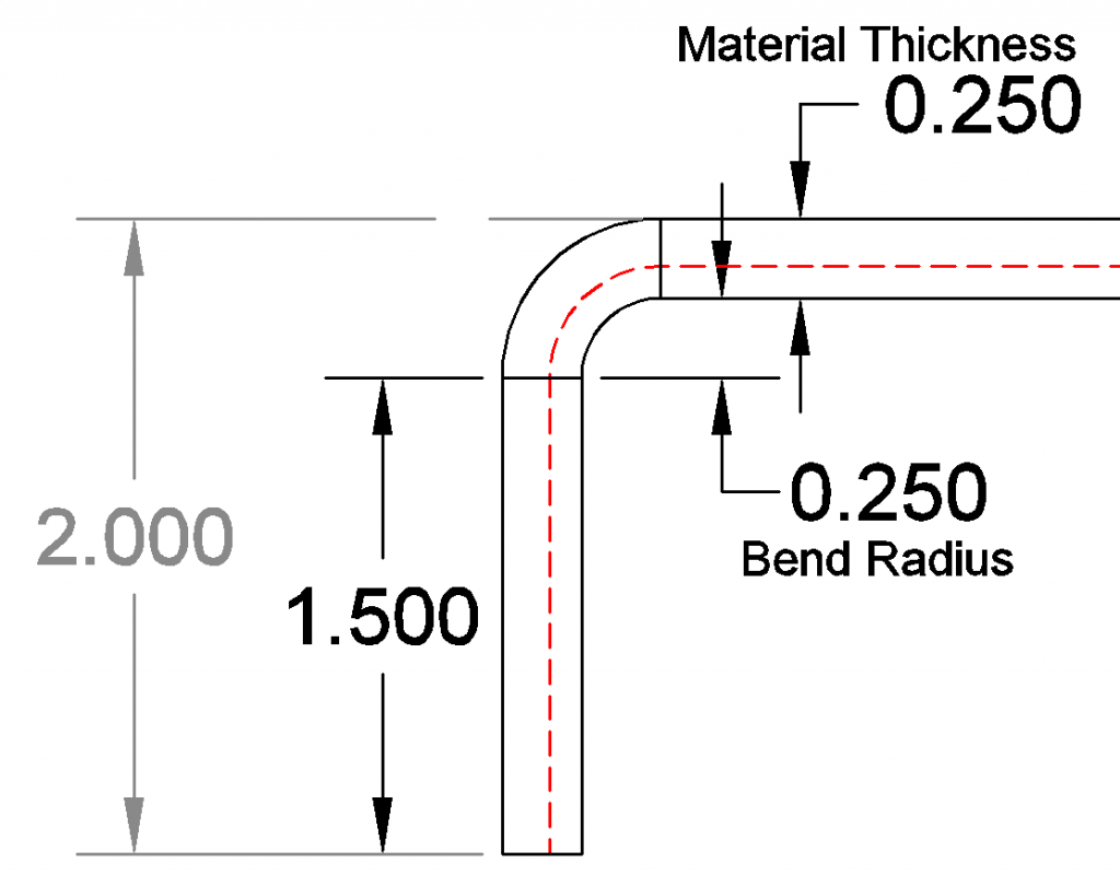
Using a K factor of .4, the neutral axis for this part is .1 inches from the inside of the bend (.40 * .25 = .10).
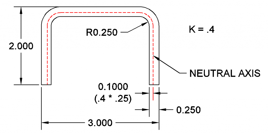
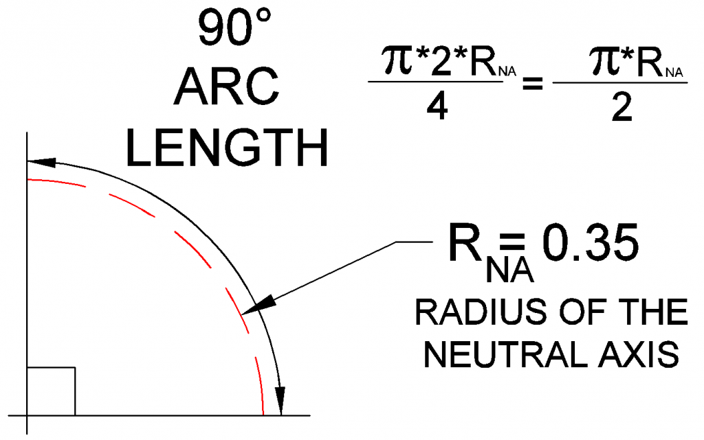
We can now calculate the radius of the neutral axis around the bends. This is the radius of the bend plus the amount of the calculated offset we found in the last step. The radius of our neutral axis inside the bend is .35 inches. This is the bend radius plus the .1 offset.
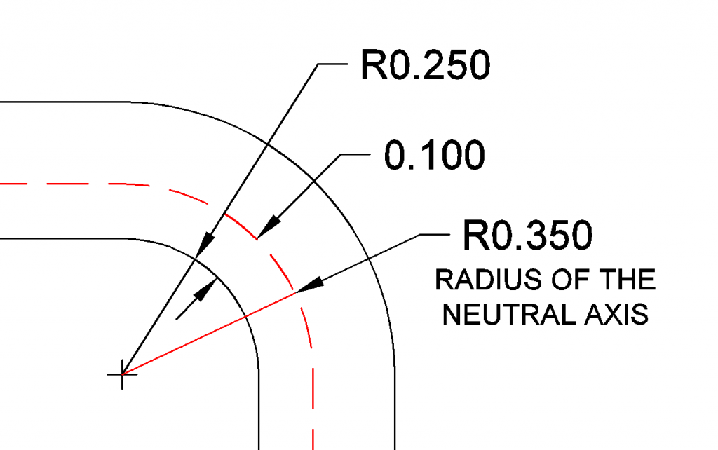
The quantity of metal to account for inside the bend is the length of the arc of the neutral axis through the bend. This is what is known as the bend allowance. It is the material “consumed” in the bend.
If the bend is 90°, you can reason that it would be 1/4 the circumference. This is pretty easy to find using logic, but it gets harder when you have angles other than 90°.
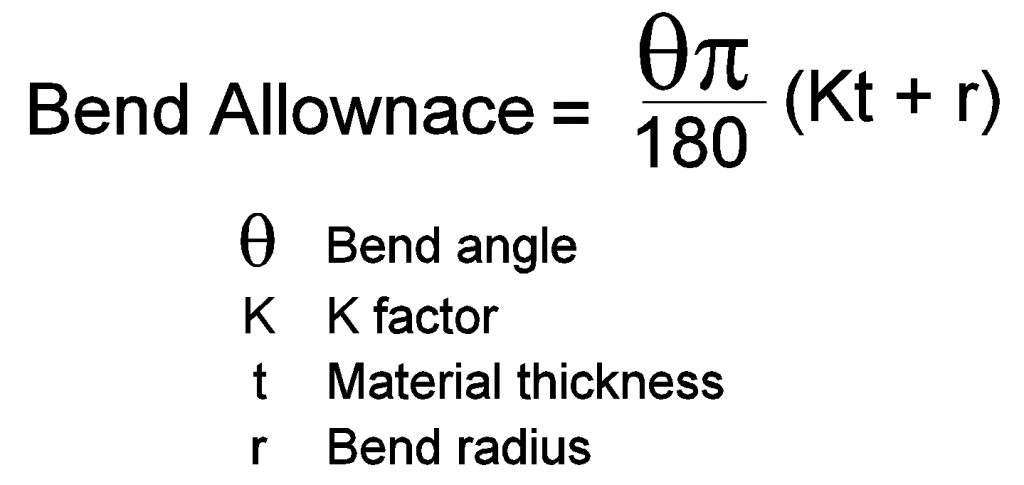
A general formula for bend allowance that works in all cases converts the angle in degrees to radians and is given below:
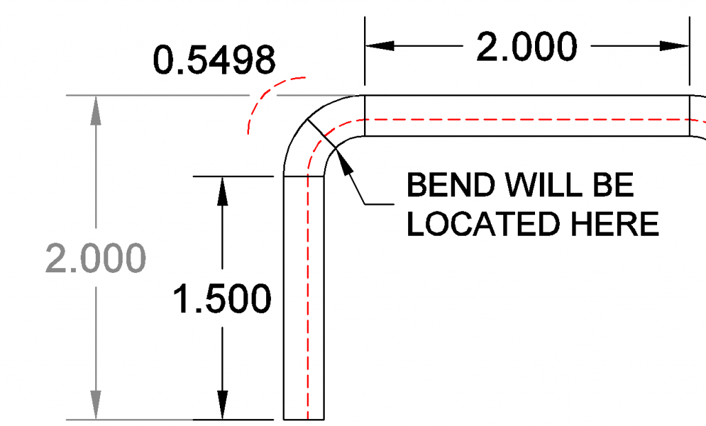
The unbent sections are found arithmetically by subtracting the bend radius and material thickness from the outside dimension.
The bend allowance is the arc length of the neutral axis. With the arc length known, we can now determine the length of the blank and the location of the bends on the blank.
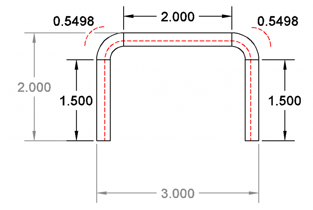
The overall blank is the length of the whole neutral axis. Here is is 1.5 + .5498 + 2 +.5498 + 1.5. This gives an overall length of 6.0996 inches.
The bend will be located halfway through the arc of the bend.
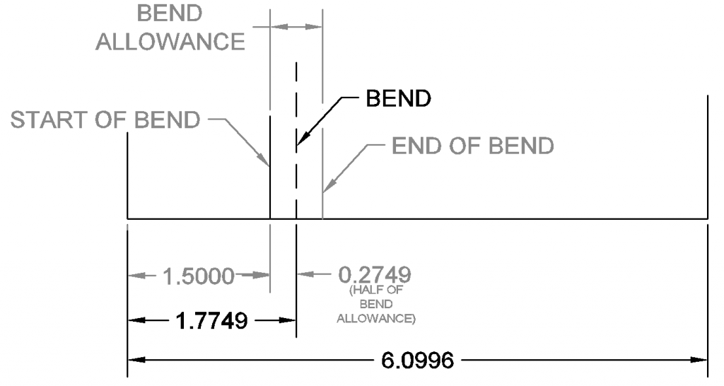
To find the location of the bend, add the distance to the start of the bend (1.5) to half of the bend allowance. The bend is centered on the arc of the bend. In the example, the first bend is located 1.7749 inches from the edge of the part. This is 1.5 + .5498/2 or 1.5 + .2749 = 1.7749.
References
“Analyzing the K-Factor in Sheet Metal Bending.” The Fabricator – Metal Fabricating News, Products, Articles, and More, The Fabricator, https://www.thefabricator.com/thefabricator/article/bending/analyzing-the-k-factor-in-sheet-metal-bending. Accessed 26 Feb. 2021.
“Analyzing the K-Factor in Sheet Metal Bending: Part II.” The Fabricator – Metal Fabricating News, Products, Articles, and More, The Fabricator, https://www.thefabricator.com/thefabricator/article/bending/analyzing-the-k-factor-in-sheet-metal-bending-part-ii. Accessed 26 Feb. 2021.


Recent Comments