
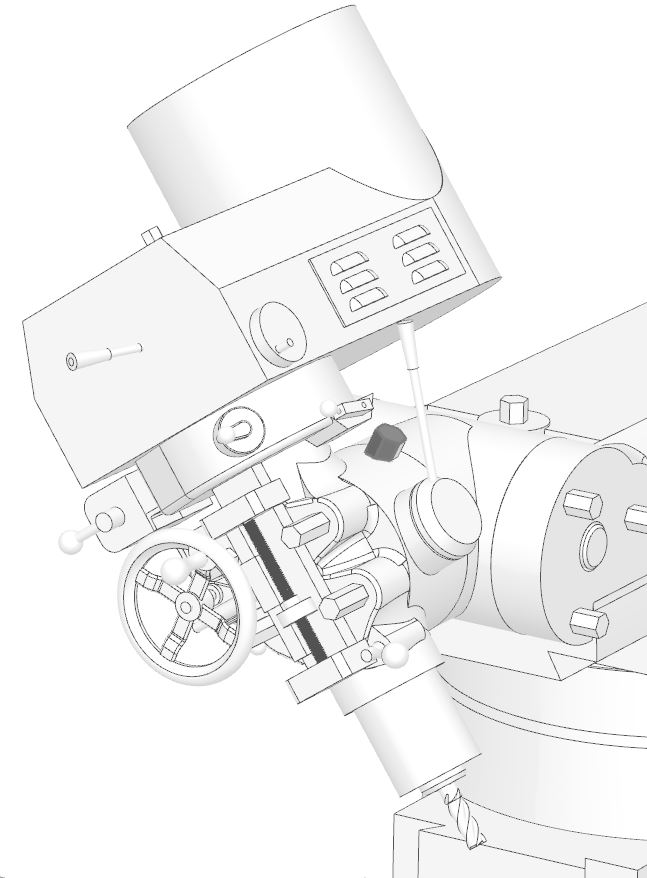
- Motor
- Switch
- Spindle
- Drawbar
- Brake Lever
- High-Low Shift Lever
- Spindle Speed Control
- Quill
- Quill Lock
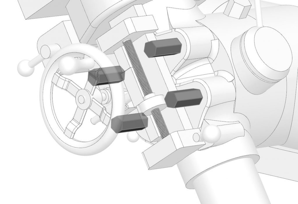
- Quill Coarse (Sensitive) Feed Handle
- Quill Fine Feed Handwheel
- Quill Power Feed Engage
- Reversing Knob
- Feed Rate Lever
- Feed Trip Cam Lever
- Quill Depth Stop
- Tilt Adjust
- Binding Studs
- Tilt Locks
Motor
The motor is the source of spindle power.
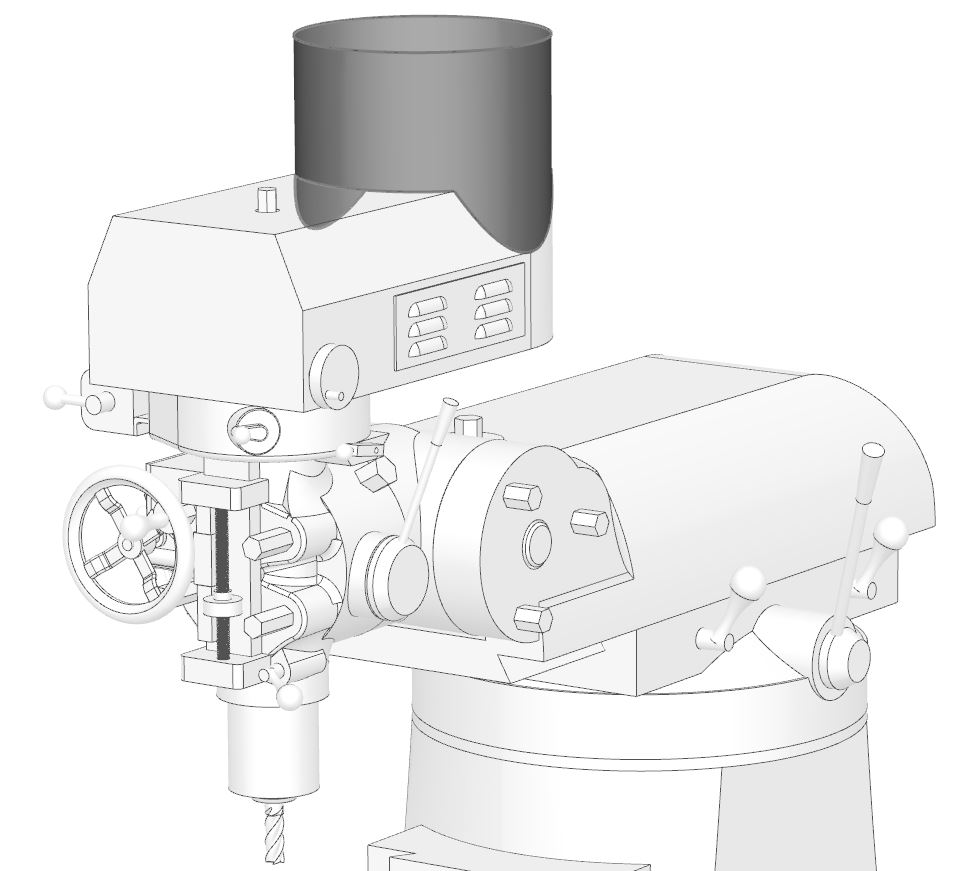
Switch
Many mills use a reversing drum switch that allows the motor to turn in either direction. The forward direction of the spindle is determined by the switch position and the High-Low shift lever (below).
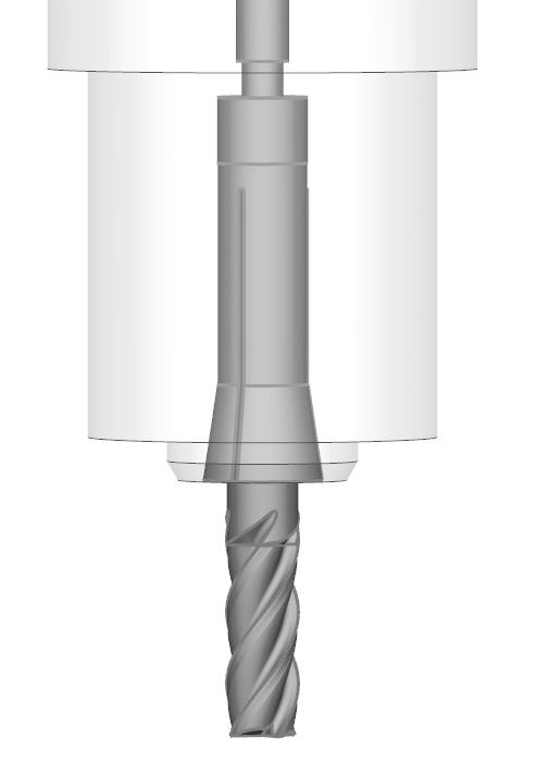
Spindle
The spindle rotates inside of bearings held in the quill. Ordinarily it has tapered nose that receives a collet or tapered tool holder.

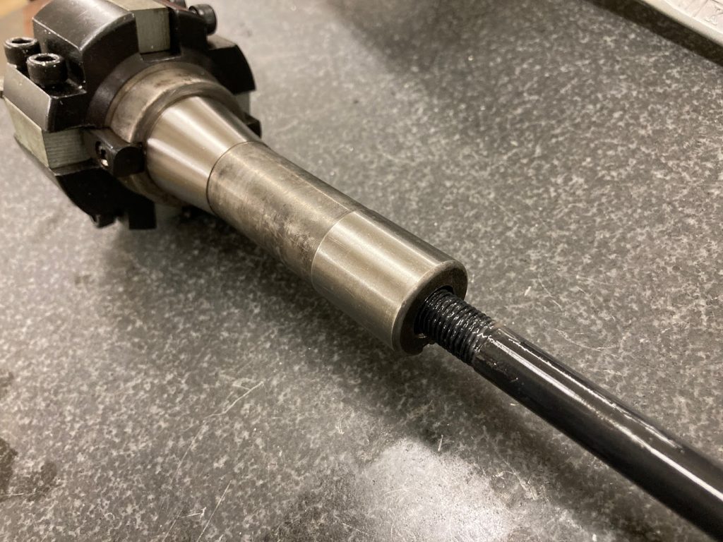
Drawbar
The drawbar threads into the top of a tool holder or collet and pulls it securely into the spindle.
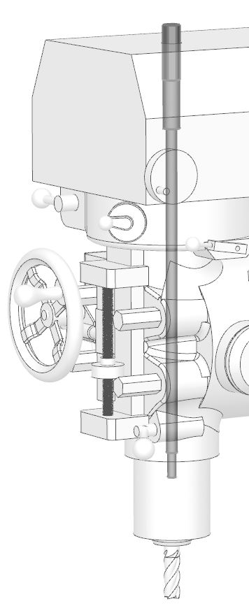
A common arrangement on manual mills is for the drawbar to be threaded into the back side of an R8 collet or tool holder.
Some mills are equipped with power drawbars for fast tool changes.
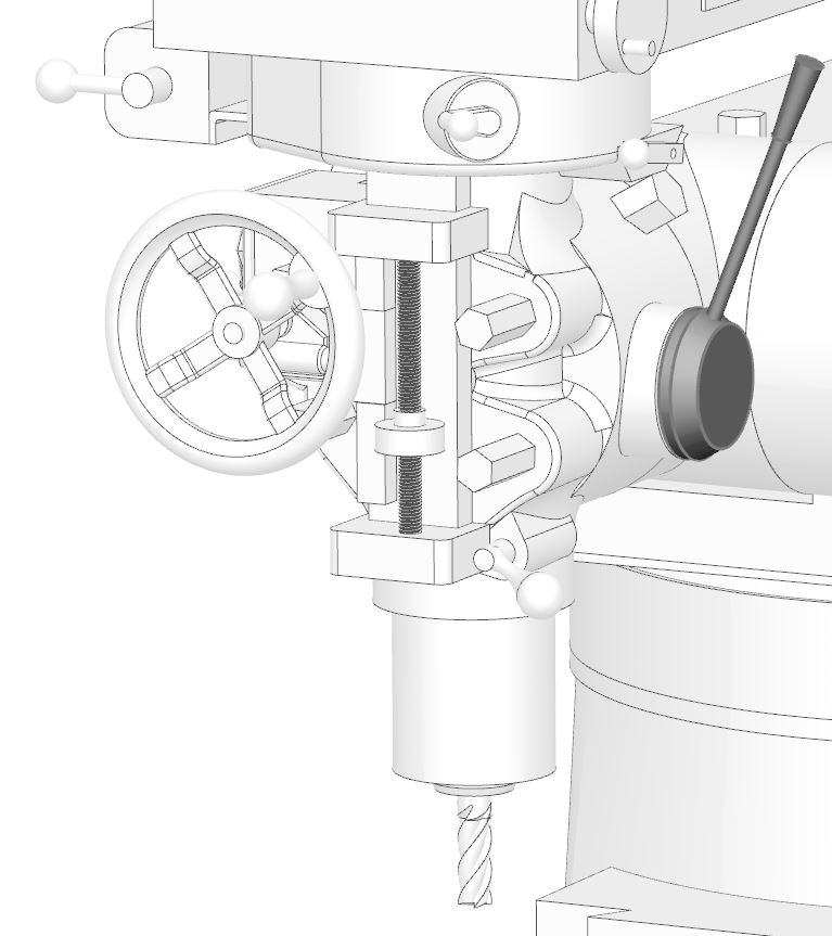
Brake Lever
The brake lever is used to slow the spindle or prevent it from turning when stopped. On some mills, the brake lever is used to keep the spindle stationary while the drawbar is tightened or loosened. This is a common method for tool changing on manual machines.
High-Low Shift Lever
Most mills are equipped with a low and high gear setting. The high-low shift lever is used to change from one to the other. Sometimes this is called the back gear lever. Putting the machine in low gear usually changes the direction of spindle rotation. The lever also has a neutral position which allows the spindle to turn freely for tooling setups.

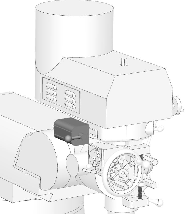
Spindle Speed Control
Spindle speed on a mill can be changed in different ways. Some mills require changing belt pulley positions, some have variable speed drives or other devices. The speed control wheel shown is for a variable speed pulley drive.
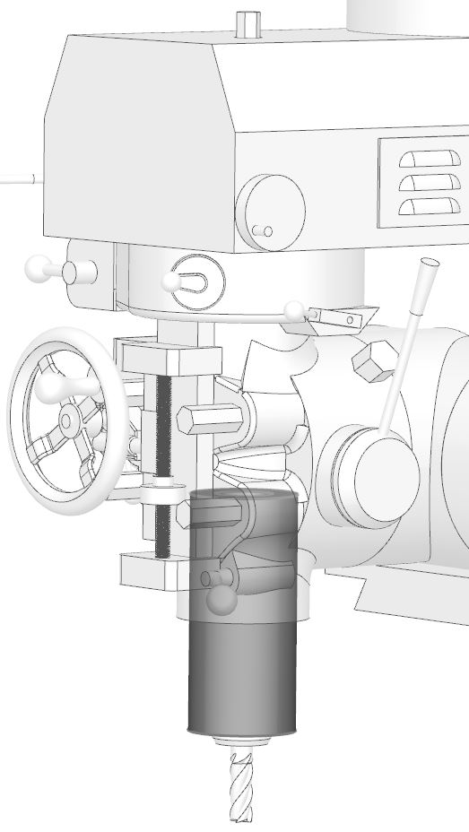
Quill
The quill houses the spindle and is free to move up and down. Many mills have a quill that can fed via powerfeed. Powered quills are often used for boring operations.
Quills can also be fed manually for operations such as drilling and tapping.
Quill Lock
For ordinary milling operations, the quill must be held securely to prevent movement. The quill lock is engaged for these operations.
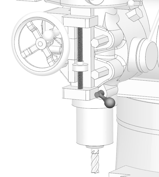
Quill Coarse (Sensitive) Feed Handle
One way to move the quill is by using quill coarse or sensitive feed handle. The quill lock must be disengaged to use the feed handle. This is the most common way to feed drills and reamers on the mill.
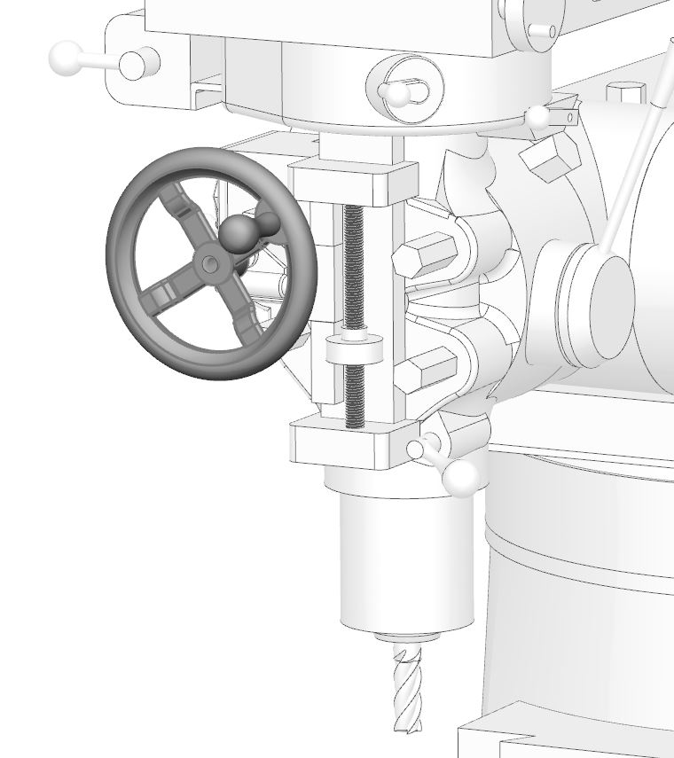
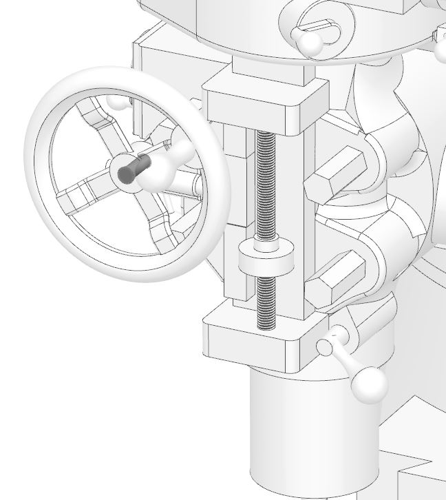
Quill Fine Feed Handwheel
The quill fine feed handwheel moves the quill with more precision than the sensitive feed lever allows. Generally, the quill powerfeed is disengaged when using the fine feed handwheel. These wheels are often removed from milling machines because they are rarely used in many industries.
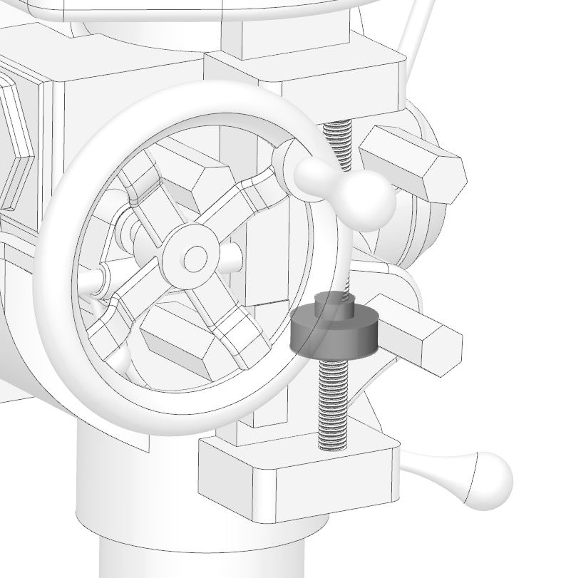
Quill Power Feed Engage
To use the quill power feed, the worm gear driving it must be engaged. However, when not in use it is advisable to disengage it to prevent wear and premature failure.
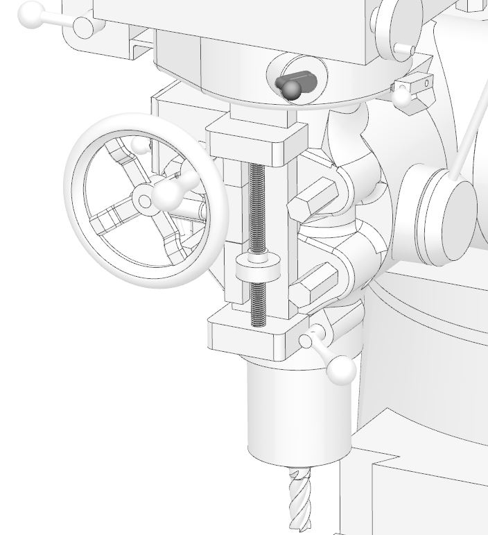
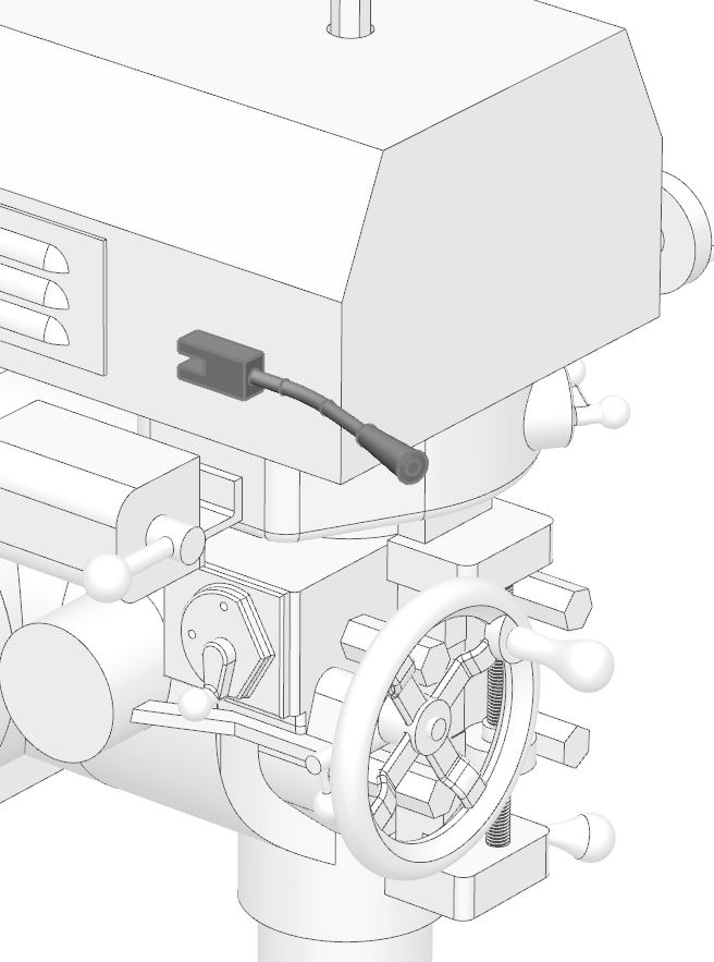
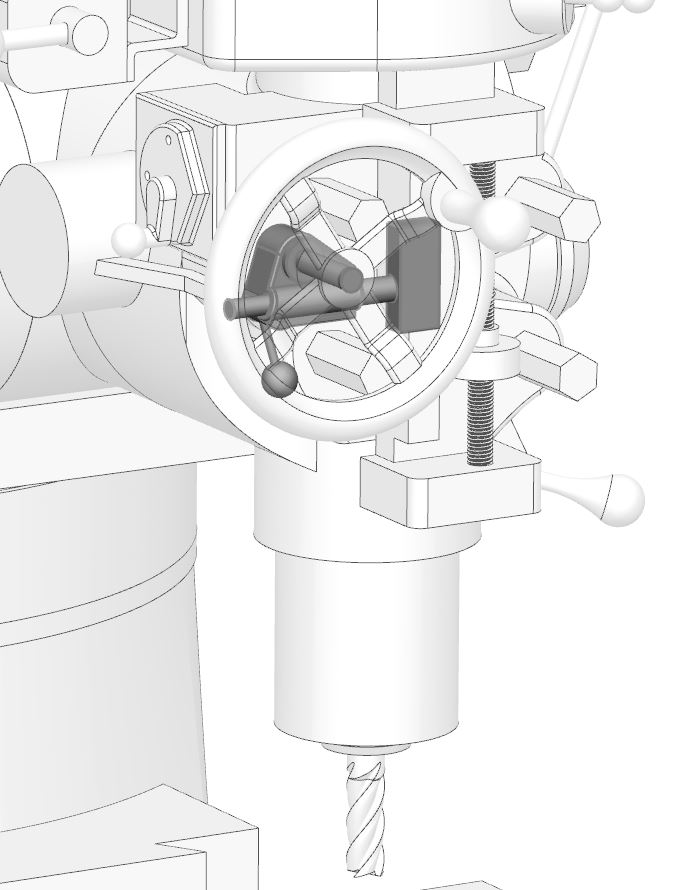
Reversing Knob
The quill powerfeed direction can be changed by pulling or pushing the reversing knob. Usually this knob is knurled and may be seen on the axis of the fine feed control handwheel.
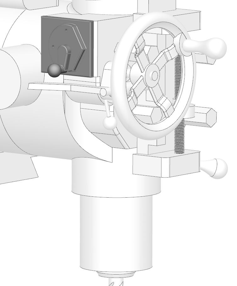
Feed Rate Lever
The feed rate of the quill power feed can be selected with the feed rate lever on the side of the head.
Feed Trip Cam Lever
The quill powerfeed can be automatically disengaged when the quill reaches a depth set by the quill depth stop. The feed trip cam lever engages and disengages the feed either manually or by striking the quill depth stop.
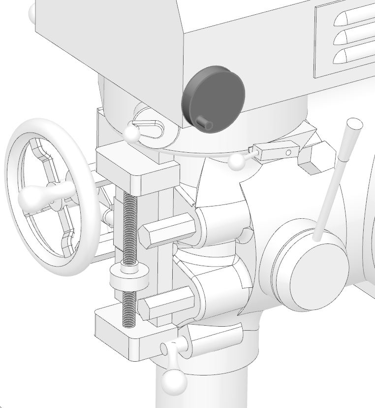
Quill Depth Stop
The depth at which the powefeed is disengaged is controlled by setting the quill depth stop. This stop is also useful for manually feeding to a particular depth.
Tilt Adjust
The head can be tilted using the tilt adjust worm drive. First the binding studs (below) are loosened. The head must be swept in whenever it is returned to its normal position.
Binding Studs
The binding studs on the front of the head casting hold the head to the head adapter and prevent it from moving. These are loosened when the head is to be tilted, but must be re-tightened carefully to prevent damage to the quill.

Recent Comments