
- Introduction
- Importance of Rigidity
- Speed
- Feed
- Depth of Cut
- Tool Shape
- Metal Removal Rate
- Specific Horsepower
- Surface Finish
- Chatter
Introduction
Cutting parameters are the changes in setup that affect the quality and efficiency of a cutting operation. Often, the optimum cutting parameter means finding the best balance between opposing factors. For example, increasing the cutting speed may decrease cycle time, but it will cause tools to wear rapidly.
Sometimes parameters can be change, and other times they cannot. For example, it might be easier to cut brass than steel, but the design intent of the workpiece may demand steel be used.
Importance of Rigidity
Among the most critical parameters is the rigidity of the setup. For a given force, the rigidity of a setup (the resistance to deflection) usually involves four variables: amount of force, shape of the member, material of the member, and the length of the member.
The member in question can be the tool, the tool holder, the workpiece, or even the machine itself. All of these must be made as rigidly as possible.
Generally speaking, the cutting force comes from the cutting action and is related to how quickly material is being removed.
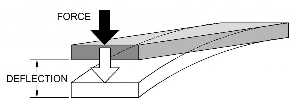
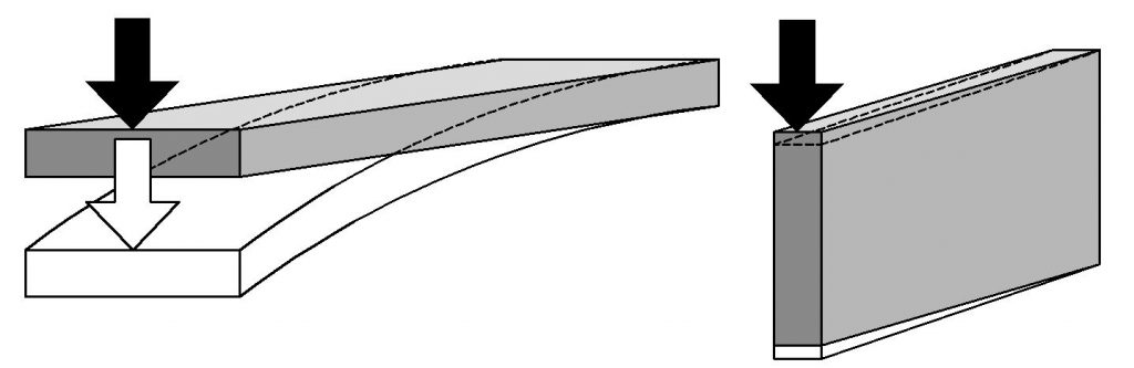
The component of strength that comes from the shape of the material is called its area moment of inertia (I). This concept will be covered later, but a larger moment of inertia results in a stronger shape. For example, a board oriented horizontally does not have as much strength to resist bending as a board turned vertically. The board oriented vertically has a higher moment of inertia than the board turned horizontally.
Young’s modulus (E) is the part of the strength that comes from the material used to make the member. A tool holder made out of plastic would be of little use because it is not a very stiff material. Steel has a higher young’s modulus, and the modulus of tungsten carbide is even higher.
Finally, and often the easiest variable to change is the length. The length that a tool extends beyond a tool holder, or the length that a workpiece extends out of the chuck has a huge effect on how a setup performs. A quick look at how deflection is calculated shows how important the length is:
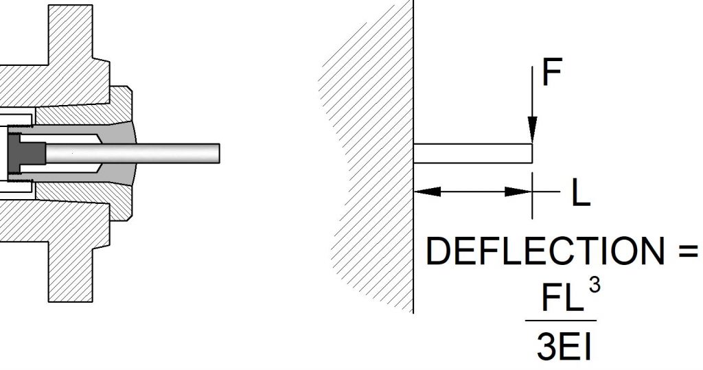
A schematic diagram of the setup shows that the length affects the deflection to the third power. Whenever it is possible, keep the length of overhang of tools, machines, and workpieces as short as possible.
One of the first symptoms that a setup is not rigid enough is chatter. Chatter is vibrations, often heard as a squealing or rattling sound. If chatter can be heard, it is leaving undesirable marks on the workpiece. Chatter is often eliminated by tightening the setup, shortening tool and part stick-out and by changing the cutting speed.
Cutting Speed
Cutting speed (often abbreviated Vc) on a lathe is the velocity of the surface of the material as it moves across the cutting tool. Velocity is measured in units of length per unit time, for example surface feet per minute (SFM) or or meters per minute.
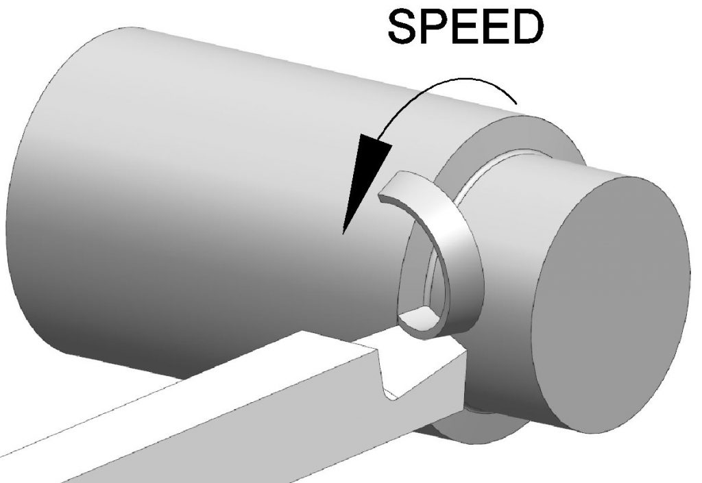
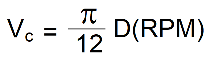
Two components make up the cutting speed, the number of revolutions the work is turning per minute (RPM) and the diameter of the workpiece at the point of cutting (D). To calculate the surface speed for a given RPM and diameter, use the equation below. A calculator is provided here for informational purposes.
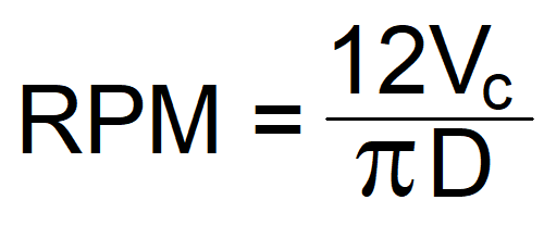
It is more common to know the desired surface speed and diameter and need to calculate the RPM. To do this, simply re-arrange the equation above to give:
Again, a calculator is available here for reference.
Choosing a suitable cutting speed involves finding a balance between tool life and metal removal rate. It depends on both the workpiece material and the tool material. There are many references for selecting an appropriate cutting speed, but one of the first sources that should be consulted is the tooling manufacturer’s recommendations. The chart below gives examples of surface speeds for various materials in SFM. Always treat suggested cutting speed data as a starting point, your actual cutting conditions will determine what speed is appropriate.
| HSS | Carbide | |
| Free machining plain carbon steels | 215 – 235 | 950 |
| Oil hardening tool steel | 125 | 590 |
| Stainless steels (Austenitic) | 115 – 135 | 570 |
| Cast Iron | 145 – 215 | 410 |
| Brass | 300 – 350 | 1170 |
| Bronze | 200 – 250 | 715 |
| Wrought aluminum | 500 – 600 | 2800 |
| Cast aluminum | 600 – 750 | 2800 |
Feed Rate
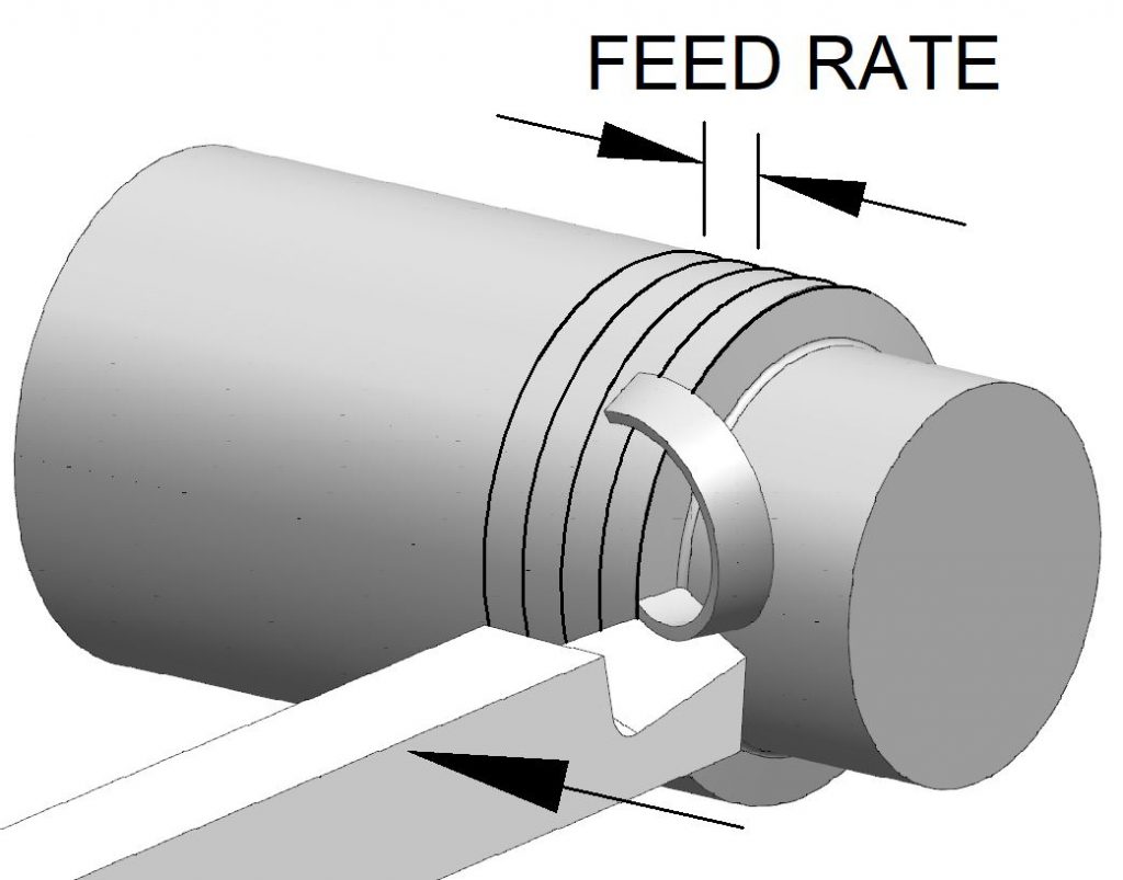
The feed rate is the rate at which the cutter advances into the work. Feed rate is given in units of length per revolution, such as inches per revolution and is often abbreviated fn. In order to achieve maximum productivity, an operator should choose the fastest feed rate that can be tolerated by machine’s power and produce an acceptable surface finish.
Depth of Cut
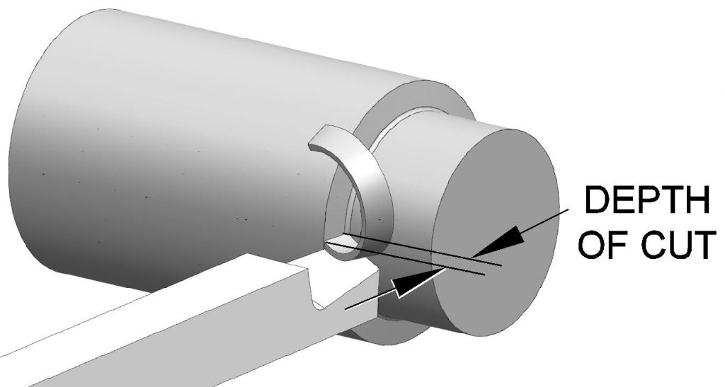
The depth of cut is the distance that the tool engages radially with the work. The depth of cut is equal to half of the diameter change between the uncut and cut cylindrical surface. Depth of cut is often abbreviated DOC or ap.
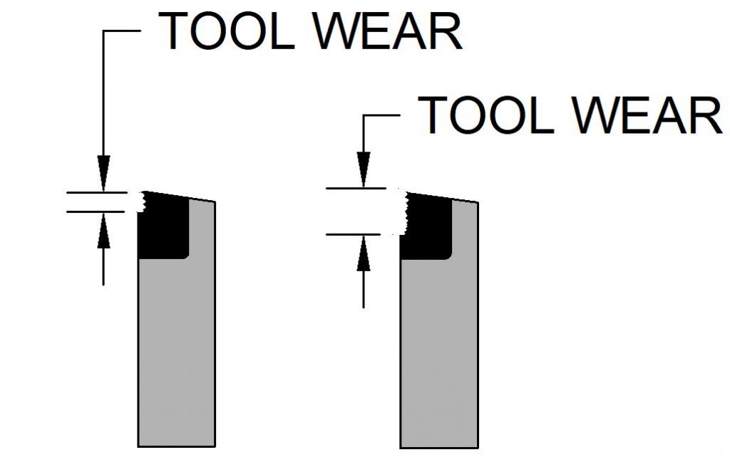
Maximizing the depth of cut can maximize tool life. This may seem counter intuitive, but consider what happens when the tool wears. A tool that has been making a small depth of cut can wear out just as quickly as one used to make large depths of cut. The difference is that the one with the larger depth of cut has removed a larger volume of metal.
Tool Shape
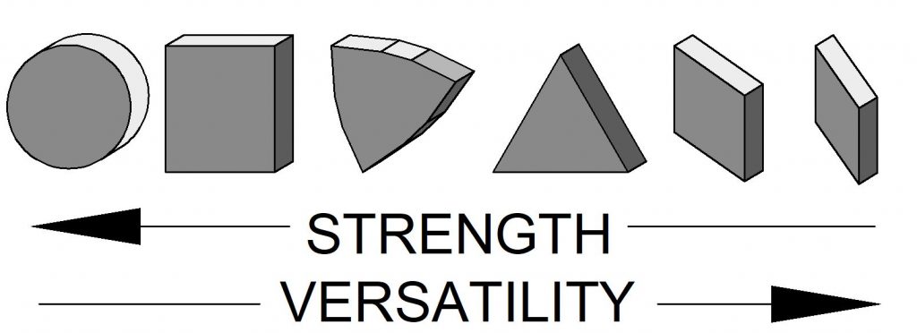
The shape of the tool can affect turning performance. Indexable inserts are available in a variety of shapes. Round and square inserts are the strongest, but are not able to produce intricate shapes.
Metal Removal Rate
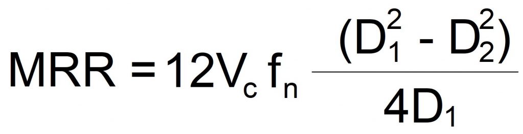
It is often necessary to calculate how long it will take to perform a particular turning operation. The volume of metal (in cubic inches) removed per minute can calculated if the cutting speed (Vc), feed rate (fn), and diameters before (D1) and after cut (D2) are known.
Horsepower Requirement
If the metal removal rate is known, it can be multiplied by a materials unit power (HPs):

Some values of HPs for common materials is shown in the table below:
| Material | Unit Power |
| Carbon Steel | 0.60 |
| Stainless Steel | 0.75 |
| Hardened Steel | 1.4 |
| Aluminum | 0.33 |
| Brass (leaded) | 0.25 |
Surface Finish
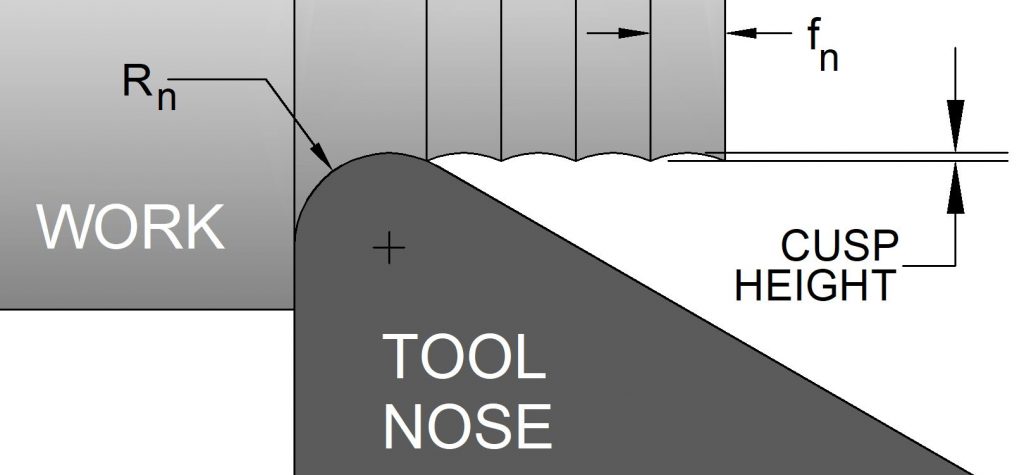
The surface finish left by a turning operation depends a great deal on the feed rate and the nose radius of the tool. Surface finish can be improved by increasing the nose radius (R) or reducing the feed rate (fn).

Recent Comments