
Introduction
Part of the job of producing engineering documentation is taking measurements of existing things. These may be mechanical components, machines, vehicles or even ships, buildings or building sites. Measurements are extremely important, and must be precise (to an appropriate level) and accurate. A precise measurement is one that is known to a small degree of uncertainty. A measurement of 1.2562 inches is more precise than a measurement of 1.25 inches. In order to make measurements with higher precision, a device with finer resolution is necessary. Resolution is the distance between marks, or the number of divisions per unit of distance the instrument can distinguish or resolve. An accurate measurement is one that agrees with a known, objective standard.
The process of ensuring that a measuring instrument agrees with the known, objective standard is called calibration. Instruments are often calibrated on a regular basis. In fact, many quality systems require that the calibration of measuring instruments used by engineers and technologists be carried out on a rigid schedule, and that this calibration be documented. In the United States, the National Institute of Standards and Technology (NIST) is the agency that makes it possible to know that a measuring instrument is making accurate measurements. Since it is expensive and time consuming to have NIST evaluate a measuring instrument the usual method is to have NIST evaluate a master instrument that is then used to calibrate other (less precise) instruments. This process can be repeated several layers deep, and a record must be kept of which instruments were used, and how far removed they are from the original NIST comparison. This record is called NIST traceability, and is essential for most any measuring instrument that is used in industry.
Units of Length
This text will focus on units of length.
Base units (dimensionally independent), derived units (combinations of derived).
Length m, mass, kg, time, s
electric current A. (note about capitalization).
US Customary
The US Customary system is familiar to most students in the United States. While the system is antiquated and cumbersome to use it is still quite popular in many industries. Even if a company is in transition to metric units there may be legacy drawings and other documentation created using US Customary units. It is essential to be fluent in both US Customary units as well as SI units (discussed below).
It is mandatory that a note indicating the units used be included on a drawing. The person using the drawing must never be forced to assume what units are being used. For example:
NOTE: ALL DIMENSIONS ARE IN MILLIMETERS.
Fractional Inches
One way of indicating lengths of less than a whole inch is t0 use fractional form. If an inch is divided into two equal parts, then each part is 1/2 of an inch. If each of these is divided into two equal parts, the result is 1/4 inch. Each quarter inch could then be divided in two to make eighths, and so on. This sequence of dividing by two is the rationale for using fractional parts of an inch. Any valid fraction of an inch will ALWAYS have as its denominator a multiple of two, e.g., 1/2, 3/4, 5/8, 13/16, etc. It is never correct to have a numerator such as 3, 5 or 7. For example, it would never be appropriate to use 2/3 of an inch.
Fractions must also be reduced to their simplest form. For instance, 8/16 would not be used on a drawing. A rule of thumb that always works with fractions of an inch is to look at the numerator. If it is even, the fraction is not in simplest form. For example, 8/16 reduces to 4/8 which reduces to 2/4 which reduces to 1/2 (now the numerator is odd, so the fraction is in simplest form). Keep in mind that this “trick” only works for valid fractions of an inch and not all fractions.
One reason that fractional inches are still used is that standard rulers and tape measures are designed to be used with fractional inches.
Feet & Inches
Feet and inch units are popular on architectural drawings. While feet and inches appear together on tape measures and yard sticks, it is important to remember that feet and inches are separate units of measure. Dimensions that use feet and inches are written as shown:

Performing calculations with feet and inches is complicated by the fact that one has to do calculations on the feet and inch units separately.
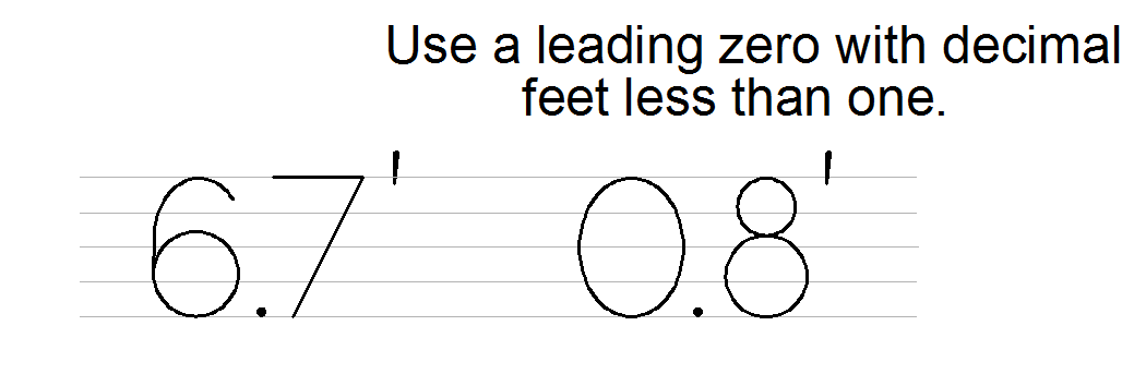
Decimal Feet
Using decimal parts of a foot instead of mixing feet and inches simplifies calculations and measurements significantly. This method is preferred in some industries that operate on a large scale. Surveyor’s tapes commonly use decimal parts of a foot. Decimal feet split a foot into ten divisions, so one and a half a feet would be written 1.5′. If more precision is required, these divisions can be divided into ten units again, such as 1.58′.
Inches will not be used on drawings that use decimal feet. The format will appear as shown below:
Be careful using a surveyor’s tape or a decimal foot. The divisions look like inches, but instead of being 1/12 of a foot, they are 1/10 of a foot.

Decimal Inches
It is common in many industries to deal only with inches and dispense with feet altogether. To use decimal inches is to divide each inch into divisions that are multiples of ten. For instance, 1.1 or 2.003 inches. Using decimal inches makes calculations easier, since the problems with adding or multiplying fractions is eliminated.

The number of decimal places (including zeros) for inch dimensions should match the number of decimal places in the tolerance. For example, if the tolerance for a .25 inch dimension was ±.01 the dimension would be written .25. If the dimension had a tolerance of ±.001, it would be written as .250.
While most rulers and tape measures are designed to work with fractional inches, most high precision measuring devices are designed to use decimal parts of an inch. Dial calipers, micrometers, and machinist scales are commonly graduated in decimal parts of an inch.
In the US Customary system decimal inch is preferred over fractional parts of an inch.
International System of Units (SI)
The International System of Units (SI) is the current version of the metric system. The base unit of length in the metric system is the meter (m). Since most design data describes components much smaller than the meter the millimeter (mm) is commonly used on engineering drawings. Centimeters are not preferred in engineering documentation.
It is important to note that the convention for leading and trailing zeros is different for millimeter dimensions than it is for inch dimensions. A zero is used in front of millimeter dimension that are less than one and trailing zeros are omitted.

The US Customary inch is defined as being 25.4 millimeters long. It is helpful to keep in mind that a millimeter is about the thickness of a dime.
Unit Conversion
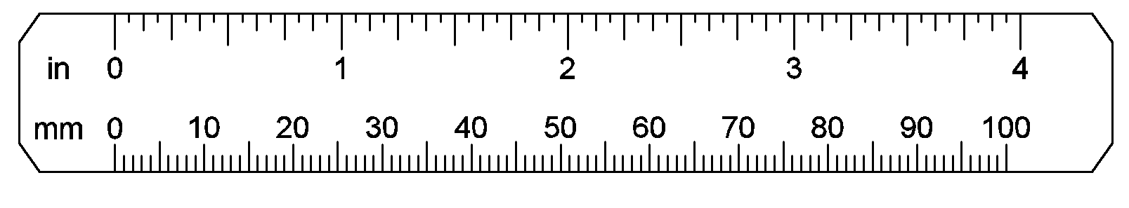
The most common length conversions in engineering design are between inches and millimeters. Fortunately, this conversion is performed by either multiplying or dividing by 24.5.
To convert inches to millimeters, multiply by 25.4.
For example, 3.0 in x 25.4 = 76.2 mm. Find this value on the rule below to get some practice seeing the difference between inches and millimeters. As a quick check think about how many dimes one would expect to be in a stack that was 3 inches tall. 76 seems like a reasonable number. If you had accidentally divided the answer (.118) would be obviously unreasonable.
To convert millimeters to inches, divide by 25.4.
For example, 100.0 mm / 25.4 = 3.937 inches. Again, it seems reasonable to guess that a stack of 100 dimes would be about 4 inches tall.
Other Calculations
While it is beyond the scope of this text, any student interested in engineering design must be familiar with the following common calculations:
- Fraction to Decimal
- Decimal to Fraction
- Adding Fractions
- Multiplying Fractions
- Calculations Involving Feet and Inches
- Square inches to Square Feet.
- Cubic inches to Cubic Feet
- Cubic meters to cubic mm
Rulers and Scales
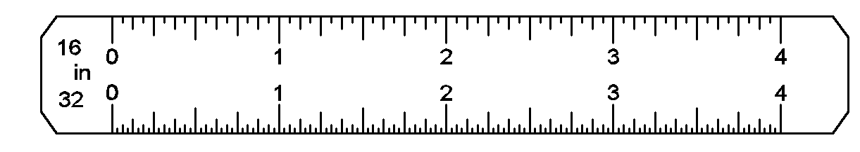
Fractional Inch Ruler
Most inch rulers divide inches into powers of two. Each inch is first divided inot two halves. Then each half is divided into quarters. The quarters are divided into eighths and so on. The most common type uses sixteen divisions but rulers with 64 divisions are available. The number of the smallest division is usually marked on the ruler, for instance, 16 — meaning each division is 1/16 of an inch.
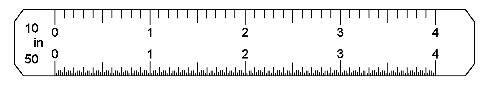
Decimal Inch Ruler
Decimal inch rulers divide each inch into ten, twenty, fifty, or even one hundred divisions. While this is unfamiliar to many students, it is much easier to perform calculations because the need for fractions is eliminated. This type of scale is common on a tool called a “machinist’s rule,” a short metal ruler common in machine shops.
Scales – indicating scale on drawing, scaling a printed drawing
Engineers’ Scale, Architects’ scale, Metric Scales
Protractors and Angular measurement
Other measuring devices (and reverse engineering).
Vernier Calipers
Dial Calipers
Micrometers
Optical Comparators
Metrology and Reverse Engineering
CMMs, Vision Systems
Surveying equipment
Angular Units
Degrees, Radians, Grads.

Recent Comments