
Most people are familiar with the rectangular (or Cartesian) coordinate system. This system of coordinate planes uses real number lines arranged at right angles to allow any point in space to be clearly and unambiguously determined. In mathematics, the order of the coordinates (separated by a comma) designates a point on the graph. For instance (2,3) would designate a point with an X value of 2 and a Y value of 3. The syntax for this point is very similar in G-Code programming. This will be discussed later in this chapter.

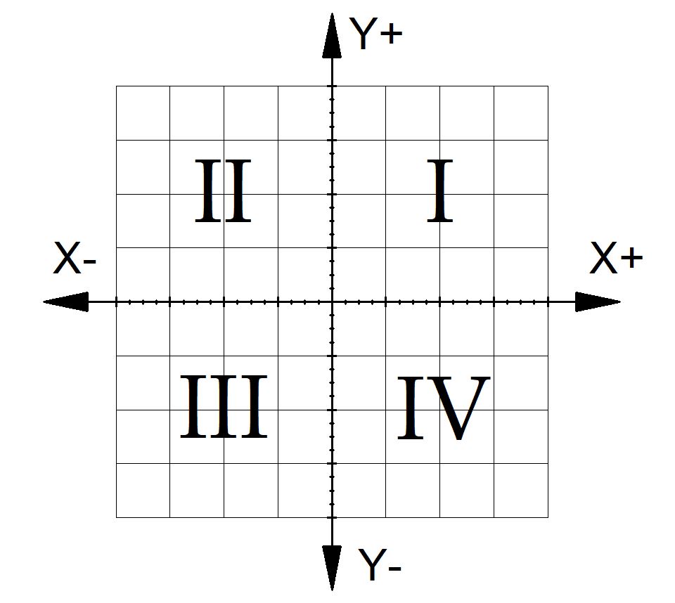
The sign of each coordinate (whether it is positive or negative) is just as important (if not more important) as the value. For example, (3,2) is nowhere near (-3,-2). It is helpful to position the coordinate grid such that it the programmer only needs to work in one quadrant. The coordinate plane (the XY plane) divides neatly into four quadrants. In the first quadrant (I) , both coordinates are positive (+,+) in the second (II), the X coordinate is negative, but the Y coordinate is positive (-,+). The other two quadrants, III and IV, work in the same way. Working in a single quadrant will help eliminate errors. When this is not possible, at least try to position the grid so that the origin is a place that would be obvious to an operator or other programmer.
Note: in three dimensional space, there are actually 8 octants.
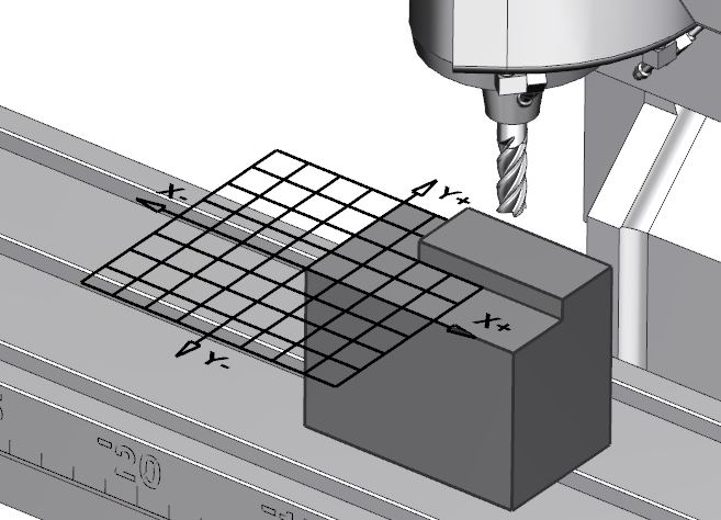
This system of planes can be overlaid on top of a machine table or workpiece to enable the machine to be directed to any point on the workpiece or machine table. In the figure below, the programmer has oriented the coordinate system so it is aligned with a particular workpiece to be cut. Since all the cutting will take place in the First Quadrant (I), the program will have all positive X and Y values when the tool is over the part.
It is the ease at which a set of Cartesian coordinates can be converted into machine-readable numbers that allows CNC to be really quite easy to program.
These coordinates correspond with machine axes. Primary linear axes are X, Y, and Z.
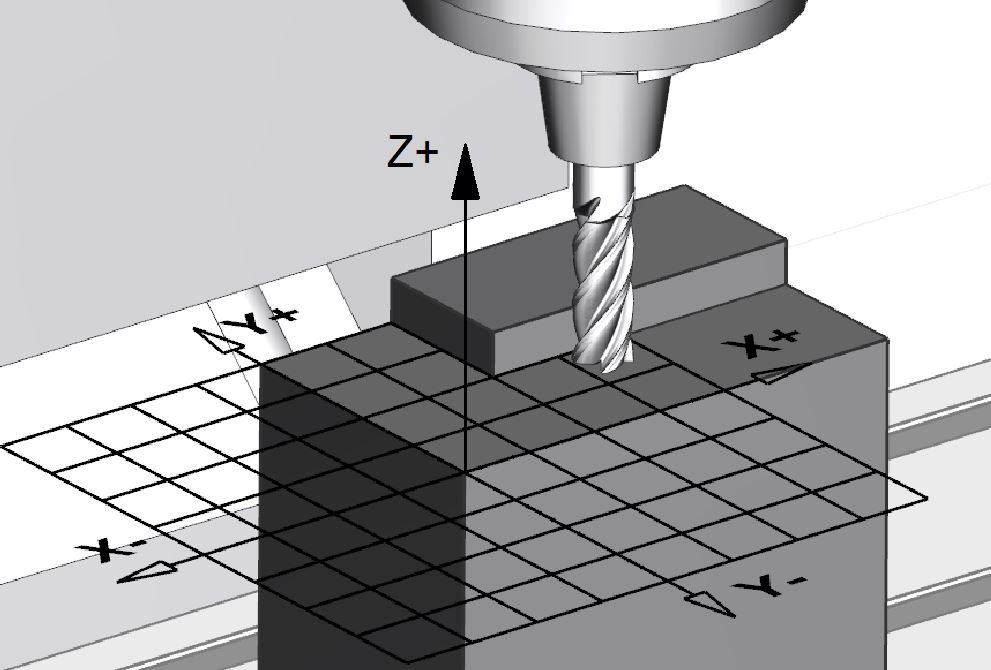
One of the first steps in programming is to be able to identify the axes of motion on the machine tool you are programming. As a general rule of thumb, the Z axis is the direction of motion that is along the axis of spindle rotation.

On a milling machine, finding the Z axis is pretty intuitive. The spindle rotation (whether it is clockwise or counterclockwise) is parallel to the Z axis. The depth of a drilled hole is usually determined by a Z coordinate.
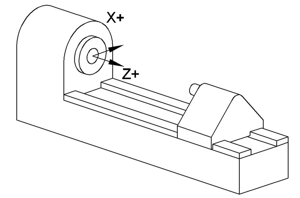
On a lathe it may be a little less intuitive, but the rule still holds. On a lathe the workpiece is mounted in the spindle by means of a chuck or other workholding device. The axis that the spindle rotates around is the Z axis. A typical two-axis lathe would have X and Z axes. The X axis typically corresponds to the diameter of the workpiece, and the Z axis corresponds to where the tool is located along the length of the workpiece.
After finding the Z axis, the X axis is usually the easiest to find. Most of the time, the X axis is parallel to the floor. The X axis will be orthogonal (at a right angle) to the Z axis. Finally the Y axis will be at a right angle to both the X and Z axis. The orientation of these three axes follows what is known as the right hand rule. If you orient your right thumb with the Z axis, the X and Y axes can be aligned with your index and middle finger respectively. The tips of your fingers will be show the positive direction of each axis.

Bear in mind that we have only discussed the direction of the axes and how they are oriented with respect to each other. The major point that we have not talked about is where the origin is for these coordinate systems. This will be discussed later in this chapter under G54-G59 – Work Coordinate System Offset (page).
Diameter Coordinate System
A special kind of rectangular coordinates are diametral or diameter coordinates. Diameter coordinates are rectangular coordinates, but one axis (such as the axis of the cross slide of a lathe) is given in diameter values rather than in an absolute distance from the origin. Lathe toolpaths are most commonly programmed using diameter coordinates.
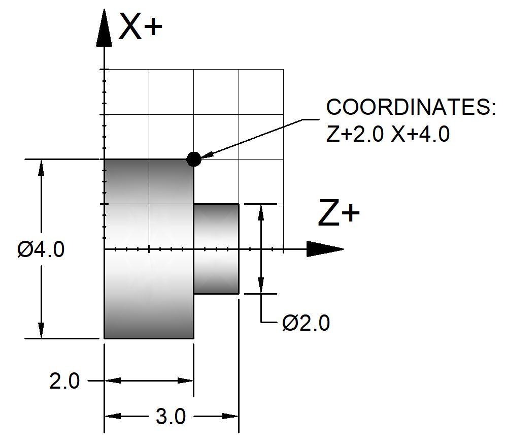
Notice this is different from an ordinary rectangular coordinate system with respect to how the X values are found. For instance, an ordinary coordinate system would assign the point shown above an X value 2.0 but a diameter coordinate system assigns a value of 4.0. This may seem unusual at first, but it is useful for programming a lathe because one axis always determines the diameter of round parts.
Polar Coordinates
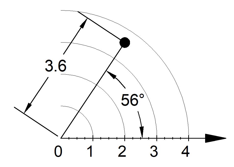
Polar coordinates define points by giving their angle (from a base line) and a distance from a particular point. Polar coordinates are commonly used to describe a circular array of holes, such as a bolt hole circle.
Many CNC machines will have a way to toggle between polar and rectangular coordinates. For example, some machines use G16 enables polar coordinates. If G16 is enabled, X values are interpreted as the radius (distance) and Y becomes the angle. On machines with this functionality G15 cancels polar coordinates and returns to rectangular coordinates.
Keep in mind that polar coordinates are not the same thing as diameter coordinates.
Work Coordinate Systems
For a coordinate system to be useful, the programmer must be able to assign the origin to a convenient place relative to the part to be machined. To define the work coordinate system origin, the programmer can position the the machine to the desired point and tell the machine that the position it is currently in should be the work origin.
The position of the work coordinate systems are often stored in an “offset register” or “offset screen.” Most machines can accommodate several different coordinate systems. The programmer can ask the machine to use one of the work coordinate systems by specifying, for example, G54.
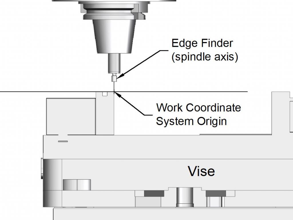
Enabling G54 through G59 is a common way to specify a specific work coordinate system. To specify the origin of, for example, G54, the operator would use an edgefinder or other probe to position the spindle over the desired origin (see below).
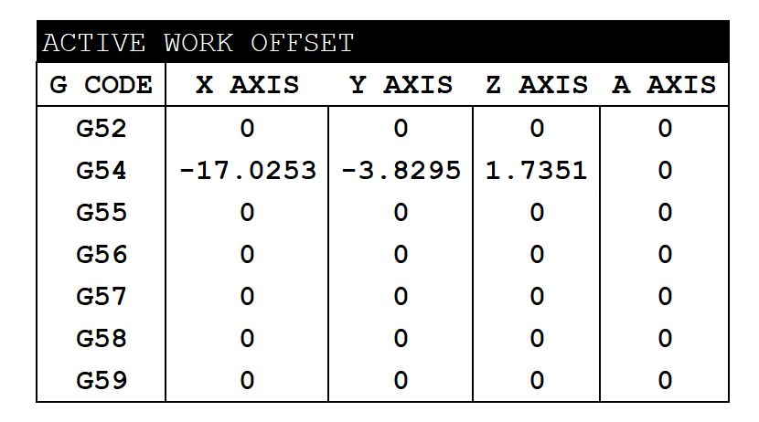
With the spindle in position, the operator would access the offset register. On a Haas machine, for example, the offset register is called “Active Work Offset” and is accessed by pressing the “Offsets” button.
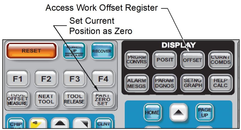
The operator would then use the control panel on the machine to assign the current X or Y location as the location of the origin. This is done on a Haas machine with the “Part Zero Set” button. The current position of the machine (in the machine coordinate system) is entered into the highlighted cell when this button is pressed.
This can be done for each of the offsets G54 through G59. When the programmer wants to use this specific point as the origin, they would enter “G54” in the CNC program.
The Z location is done in a similar way, but has to account for the length of the tool being used. This will be discussed later.
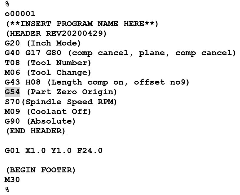
To enable a particular work offset, the programmer would enter the value in the program. For example, the program below would use G54 as the program origin.
The Machine Coordinate System
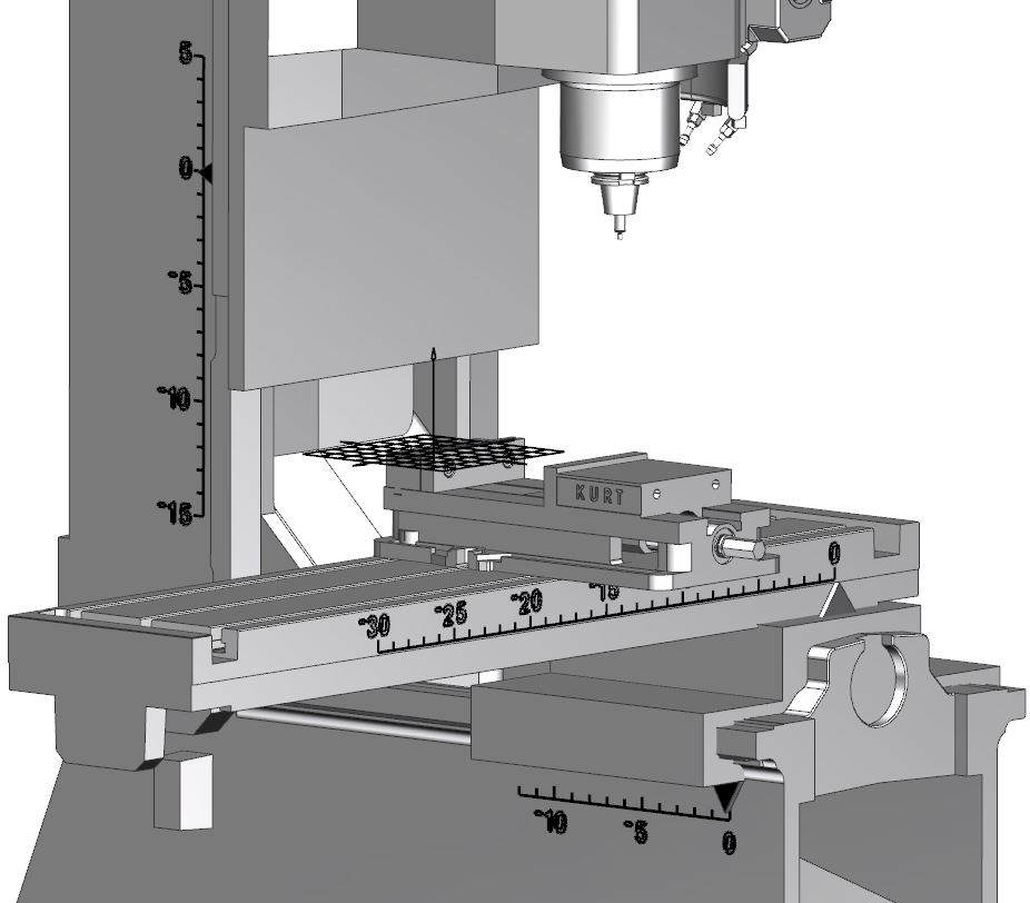
Every CNC machine tool is made with its own built-in coordinate system. Many times when a machine is powered up, it will move all its axes to its own machine home. This is usually its own machine coordinate system zero. This system is built in by the machine tool builder and cannot be altered. It is possible to (but pretty uncommon) to mark the machine’s coordinates physically on the machine. I do this to help students understand the concept. The model below has had the machine coordinate system labeled on the axes.
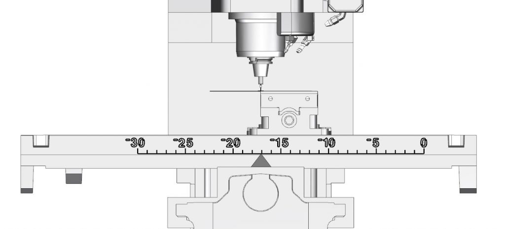
The spindle is currently positioned at the G54 origin shown on the offset register above. Notice the value in the offset register is -17.0253, which is point on the labeled X-axis on the machine tool.
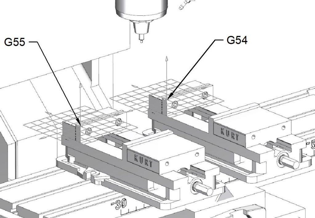
In some cases, a programmer may need more than one coordinate system origin. A common example is shown below, where there may be multiple fixtures on a machine. One vise can be assigned as G54, and the other may be G55.
Machine Origin and Machine Home
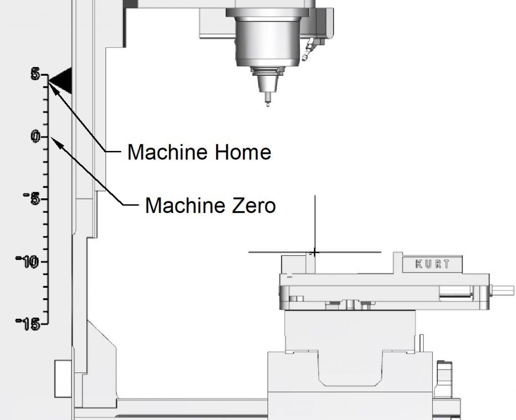
As mentioned before, when most machines are powered up, they return to their “home” position. While this is often the machine coordinate system origin, it is not necessarily so. The machine tool below is positioned at its origin.
Notice that the Z axis can extend beyond this by over four inches. When this machine goes to its home position, it is a little above its origin in the Z axis.
Here the machine is shown at its home position. Notice the Z axis is above the machine origin.
It may be easier to see how the G54 offset works with the machine at its origin position. Notice how far the spindle is from the G54 origin when it is at its home position:
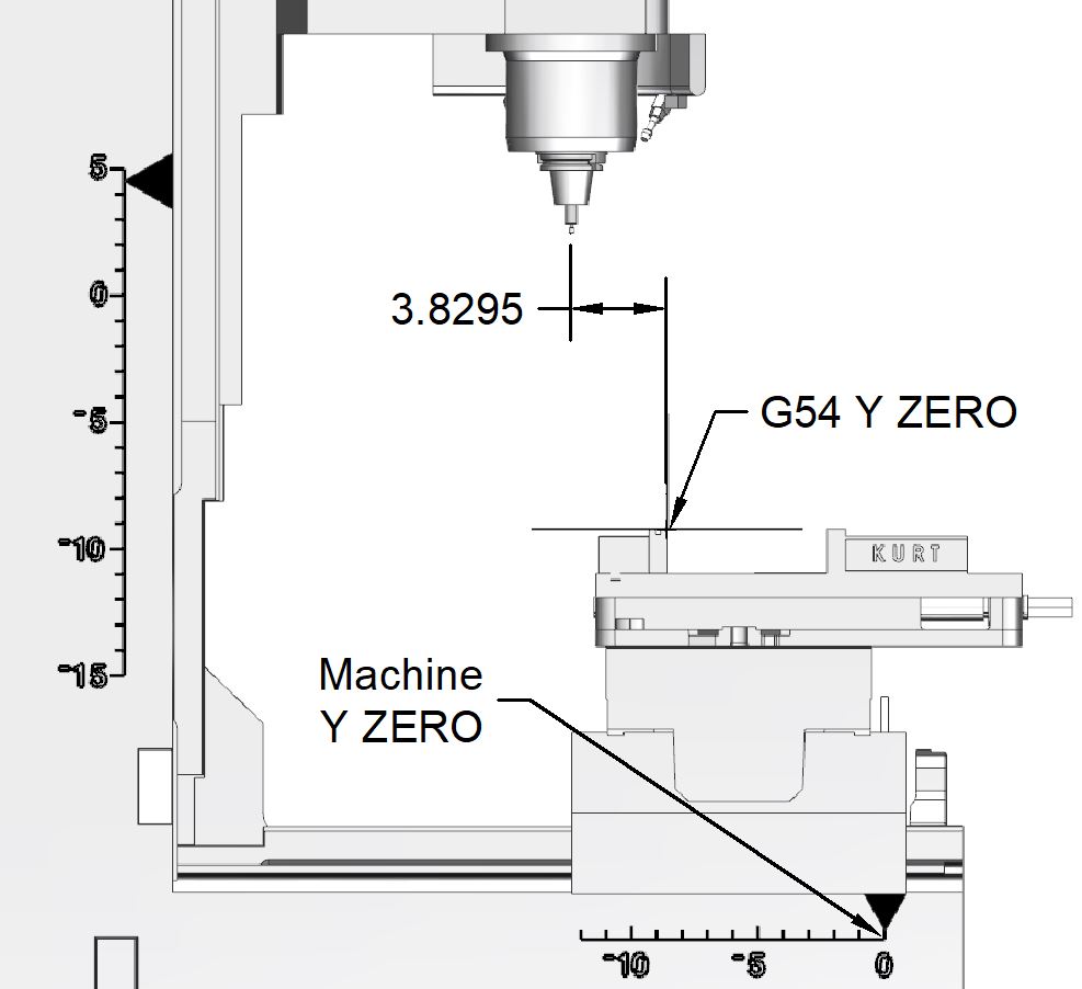
Here it can be seen why the value in the offset screen is -3.8295. When the machine is at its own Y axis origin, it is 3.8295 inches away from the G54 Y axis origin.
Movement in Positive and Negative Direction
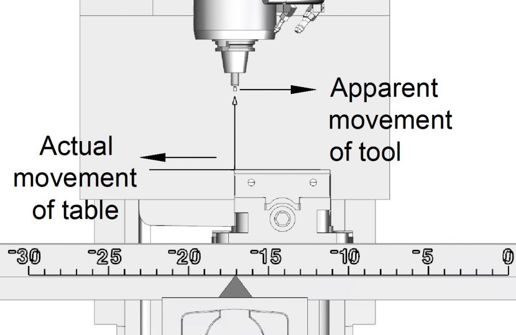
It is sometimes a source of confusion as to which direction is positive motion on a CNC machine. It is simple enough to understand that positive movement is typically from left to right. However, it is important to keep in mind that this is with reference to the spindle/tool movement. Often, the table moves while the spindle is stationary. In the diagram below, the X axis is jogged in the positive direction. This means the table moves from right to left. This has the effect of moving the tool in the positive direction.
This is extremely important to understand when doing setup work and manually jogging the table.

Recent Comments