
Thread specifications are standardized by form and series. Using standard thread specifications allows designers to design threaded assemblies that have appropriate allowance and tolerance for the desired application. Where standard allowance and tolerances are not appropriate, they can be specified in a notation.
This section will look at standard specifications for two of the most common thread forms:
- Unified Inch and
- Metric.
Unified Inch Screw Threads
Two of the Unified screw thread forms (UN and UNR) are standardized in ASME B1.1 -2003. UNR only applies to external threads and mandates a radius on the root of the thread.
Unified Thread Designation
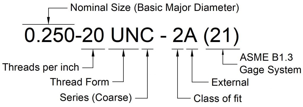
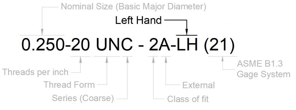
A Unified thread designation is structured as follows:
- Nominal size
- Number of threads per inch
- Optional: Lead & number of starts (for multiple start threads).
- Thread form symbol (UN)
- Thread series symbol (e.g., UNC)
- Thread class symbol (1, 2, or 3)
- External or Internal (A or B)
- Optional LH for left-hand threads
- Gaging system (from ASME B1.3)
NOTE: This information is for reference only. See ASME B1.1 – Section 6 for definitive information regarding screw thread designation for Unified threads. See Terms of Use.
Nominal Size
The nominal size of a Unified thread is the basic major diameter. It can be designate as a fractional diameter (e.g., 1/4), a screw number (e.g., 10), or the decimal equivalent of these (0.250, 0.190).
Threads per Inch
The number of threads defines the pitch. The pitch is the distance from one thread to the next, so the number of threads per inch is the inverse of the pitch. For example, a 0.250-20 UNC thread has 20 thread per inch. The pitch for this thread would be 1/20 of an inch or 0.05 inches.
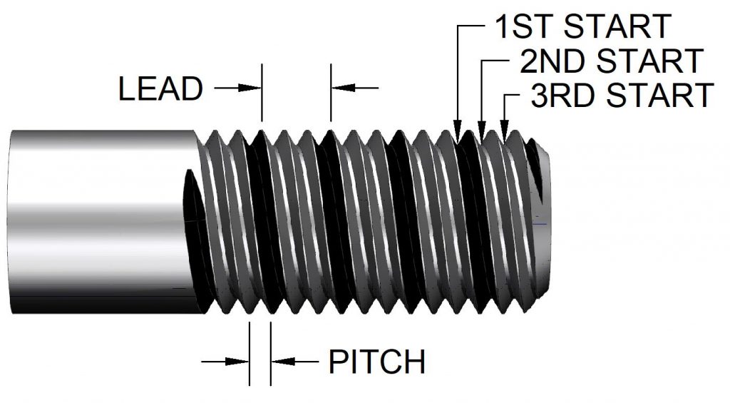
Lead & Number of Starts
The lead and number of starts is only specified on threads with multiple starts. Multiple start threads are used when more axial motion per revolution is required. Since the lead is different from the pitch on multiple start threads it is included in the designation. Notice in the example below that the lead (0.1875) is three times larger than the pitch (1/16).

A three start thread has three individual thread grooves, each 120 degrees apart around the circumference.
Thread Form Symbol
Unified threads are a particular shape of thread. This shape is defined by a mathematically defined path called the basic form. The standard Unified Thread Form (ASME B1.1) also defines the amount of allowance between mating thread forms as well as limits of size, standards for designation. See Thread Form.
Series
The series of a thread form is diameter and pitch combinations that are available. The Unified Thread form has two categories of standard series: Graded pitch series (coarse, fine, and extra fine) and Series with uniform (constant) pitch series. Special series (UNS or UNRS) may also be specified.

Graded Pitch Series
The three Unified graded pitches are as follows:
- (UNC or UNRC) Coarse
- Coarse threads are used in general purpose applications.
- (UNF or UNRF) Fine
- Used for high-strength applications, where finer adjustment is needed, or for thinner walls are necessary.
- (UNEF or UNREF) Extra fine
- Extra fine threads are used where fin adjustment is necessary such as adjusting screws, or thin-wall tubing or thin nuts are required.
Constant (uniform) Pitches
If pitches other than those available in as graded pitches are required for a design, constant or uniform pitches can be specified. Using the constant pitch series allows production of standard thread pitches to be used in combinations not defined by the graded pitches. Constant pitches can also be used with diameters that are not preferred for production.
Special Series
Specifying a special series (UNS or UNRS) allows a designer to request threads that have allowances and tolerances that are defined by the Unified Thread Standard, but do not conform to standard diameter and pitch combinations. UNS thread designations must include limits of size.
If allowance and tolerance are also non-standard, the UNS or UNRS must not used and is replaced with “SPL 60 degree Form.”
Notice that the thread note for an SPL form does not use UN or the word Unified. It also defines the thread as external by EXT instead of the A symbol.
Class
Thread classes define how much allowance is required between mating threads, and how large the tolerance zone is for the male and female threads.
Since these values are different for internal and external threads, each class identifier (1, 2, or #) must include either an A or B to distinguish between external and internal thread limits.
- Class 1A and 1B
- Liberal tolerance and allowance.
- Easy assembly and disassembly
- Work when slightly damaged
- Not used frequently
- Class 2A and 2B
- Common class for general purpose
- Often the class of nuts, bolts and screws
- Class 3A and 3B
- No allowance built in.
- Possible for internal and external to match size exactly.
- Combinations of Class
- Classes can be combined for different design requirement.
- For example, Class 2A external bolt can be used with a 1B, 2B, or 3B nut.
External or Internal
Because they are designed to be assembled together, thread dimensions are different for internal and external threads. To distinguish between the two, the letter A is used to designate external thread and B is used to indicate internal threads. The A or B symbol is actually part of the class symbol See class above.
Left-Hand Threads
If a left-hand thread is required, the symbol LH is included after the class of fit and internal. Right hand threads are the default and do not require a symbol.
Thread Gaging System
The (21) at the end of the note is from ASME B1.3
Recent Comments