
Carriage
The carriage is the main means of controlling cutting tool movement. There are two major components to the carriage, the saddle and the apron.
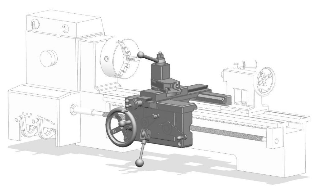
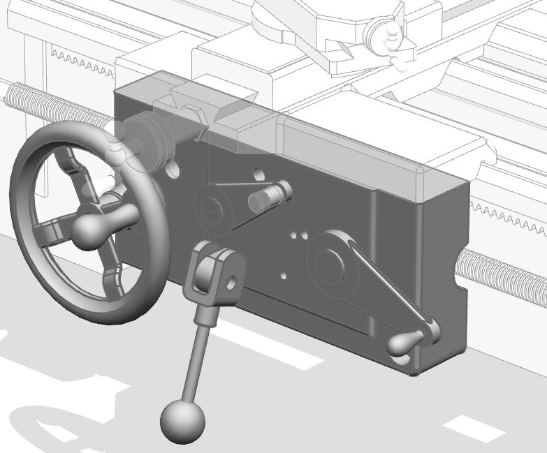
Apron
The apron is the structure is located on the front face of the carriage. The apron is responsible for receiving power from the lead screw or the feed rod and transferring it to power either the carriage itself or the cross slide.
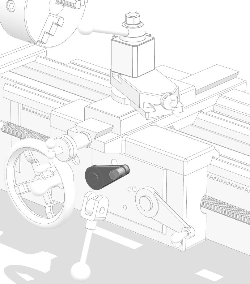
Power Feed Clutch
The power feed clutch is the disconnect between the feed rod and the apron drive train. It is only used when feeding using the feed rod to power either the carriage feed (in the Z direction) or the cross slide (in the X axis). It is not used for threading operations. For threading, the half nut lever is used.
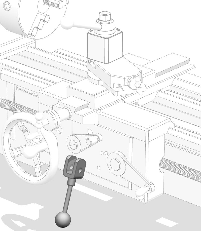
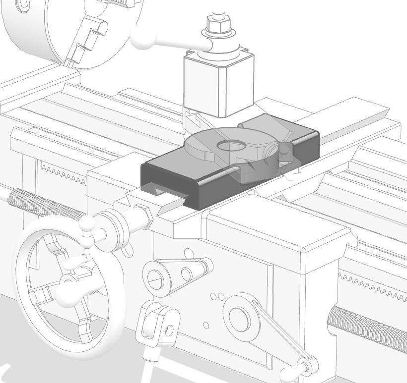
Power Feed Select
The power feed select is used to control whether power goes to the carriage feed, the cross slide feed, or neither. The power feed select must be in the neutral (neither) position when threading.
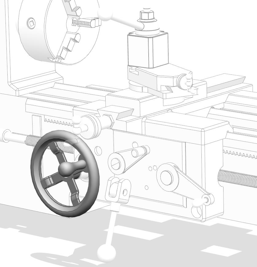
Carriage Handwheel
The carriage handwheel is used to manually position the carriage along the bedways.
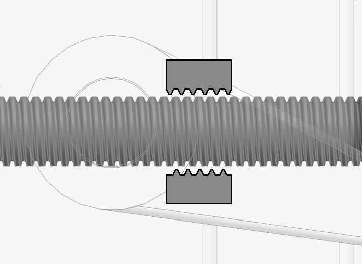
Half Nut Lever
The half nut (or split nut) lever is used exclusively for threading. It closes a two piece ACME drive nut down onto the lead screw. To use the half nut lever, the power feed select must be in the neutral position, and power must be supplied to the lead screw instead of the feed rod. On many lathes there is an interlock to prevent accidental engagement of the half nut onto the lead screw. Damage may result to a lathe that has been improperly set using the half nut, so never engage this lever without proper training and caution.

Saddle
The saddle is the part of the carriage that rides on the bedways. It supports the cross slide which in turn supports the compound rest and the toolholder.
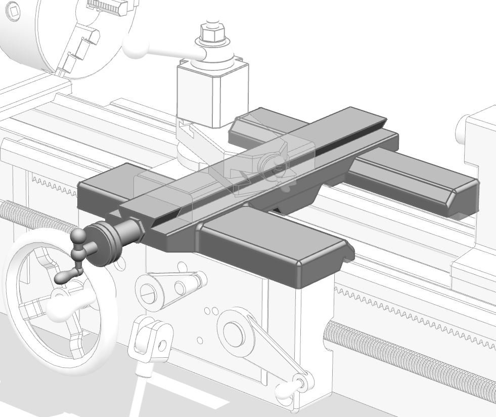
Cross Slide
The cross slide moves the tool in the radial direction with respect to the workpiece. This is usually referred to as the “X” axis. Diameter changes result from motion in the cross slide direction. Most lathes have power feed available in the cross slide direction.
Cross Slide Handwheel
Although power feed is usually available to the cross slide, it is often convenient to position the tool manually. The cross slide handwheel is provided for this purpose. Turning this handwheel moves the cross slide in the radial direction with respect to the workpiece and will result in a diameter change.

Compound Rest
The compound rest is used to make tapered cuts. Tapers are conical features that cannot be cut (on manual machines) by using the orthogonal motion of the carriage and cross slide. In general, CNC lathes do not have a compound rest because tapered motion is achievable under computer control by moving the carriage and cross slide simultaneously. Most lathes do not have a power feed available to the compound rest.
The angle of the compound rest is adjusted by loosening two or more binding screws and rotating the compound.
Compound Rest Handwheel
The compound rest must be fed with a handwheel because it generally does not have power feed available.

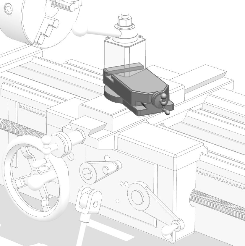
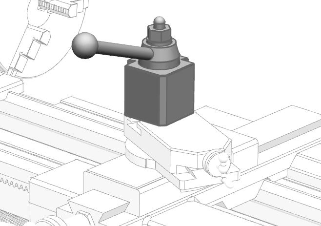
Toolpost
The toolpost is fitted to the compound rest and provides a means of holding the cutting tools. Manual lathes may have a variety of toolpost. A quick-change toolpost like the one shown here is a convenient way to change tools. See more about lathe tools and tool holding here.

Recent Comments